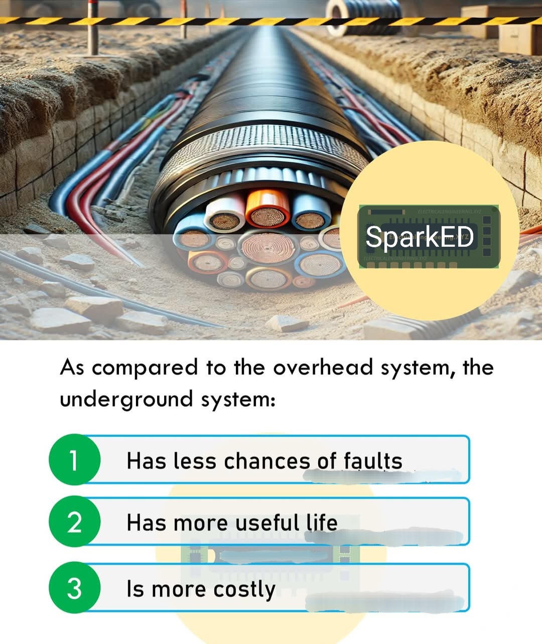
1. Has less chances of faults
2. Has more useful life
3. Is more costly
Let's analyze each statement based on general knowledge about underground vs. overhead systems:
1. Has less chances of faults:
Underground systems are generally less prone to faults because they are protected from environmental factors like weather (storms, lightning, wind), falling trees, or accidental damage from vehicles. Overhead systems, on the other hand, are exposed and more susceptible to such issues. This statement is true.
2. Has more useful life:
Underground cables are typically more durable over time since they are shielded from weather-related wear and tear, UV radiation, and physical damage. While maintenance can be more challenging, their lifespan is often longer than overhead systems, which degrade faster due to exposure.
This statement is also true.
3. Is more costly:
Installing an underground system is generally more expensive than an overhead system. It involves digging trenches, laying cables, and ensuring proper insulation and protection, which increases labor and material costs. Overhead systems are cheaper to install since they use poles and simpler infrastructure.
This statement is true as well.
Answer:
All three statements are correct:
- The underground system has less chances of faults.
- The underground system has more useful life.
- The underground system is more costly.
If this were a multiple-choice question where you need to pick one, the most emphasized difference in many contexts is often the cost (statement 3), but since the question doesn't specify, all three are accurate based on the comparison.