Saturday, 14 December 2024

HVAC and HVDC cost comparison

This image compares the costs associated with High Voltage Alternating Current (HVAC) and High Voltage Direct Current (HVDC) transmission systems as a function of distance. Here’s a breakdown of the graph and a brief overview of the concepts:

Key Components of the Graph:

1. Axes:
   - X-Axis (Distance): Represents the distance over which electricity is transmitted.
   - Y-Axis (Cost): Represents the cost of transmission systems.

2. Cost Lines:
   - HVAC Cost Line: This line typically shows a steeper slope, indicating that the cost of HVAC systems increases significantly with distance. HVAC systems are generally more expensive to maintain over long distances due to higher energy losses.
   - HVDC Cost Line: This line has a gentler slope, indicating relatively lower costs over long distances. HVDC systems become more cost-effective as the distance increases, primarily due to reduced transmission losses and lower infrastructure costs over long spans.

3. Economic Crossover Point:
   - The point where the two lines intersect is referred to as the "economic crossover." This point indicates the distance at which HVDC systems become more economical compared to HVAC systems. Beyond this distance, HVDC is typically the preferred choice for transmission.

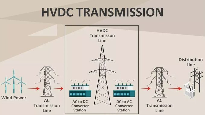
Overview of Concepts:

The graph illustrates the economic viability of HVAC and HVDC transmission systems based on distance. In general:

- HVAC Systems: Suitable for short to medium distances, with significant energy losses over longer distances. Their costs increase rapidly as the transmission distance grows.
  
- HVDC Systems: More efficient for long-distance transmission due to lower energy losses and reduced infrastructure requirements. They become the more economical choice as the distance increases, making them ideal for connecting remote renewable energy sources to the grid.

Overall, this analysis highlights the importance of choosing the appropriate transmission technology based on distance, which is crucial for optimizing costs and improving the efficiency of power delivery.

High voltage direct current HVDC transmission

This is the concept of High Voltage Direct Current (HVDC) transmission, which is an efficient method for transmitting electrical energy over long distances.
Here’s a brief explanation of the key components and the overall concept:
Key Components:

1. Wind Power Generation:
   - The process begins with wind turbines generating electricity. This is typically in the form of Alternating Current (AC).

2. AC Transmission Line:
   - The generated AC power is transmitted through high-voltage AC transmission lines. This is the traditional method of electricity transmission.

3. AC to DC Converter Station:
   - At a strategic point along the transmission line, an AC to DC converter station transforms the AC power into High Voltage Direct Current (HVDC). This conversion is essential for long-distance transmission as DC power experiences lower losses compared to AC.

4. HVDC Transmission Line:
   - The HVDC transmission line carries the high-voltage direct current over long distances. This method is particularly beneficial for reducing energy losses and improving the stability of the power grid.

5. DC to AC Converter Station:
   - Upon reaching the destination, another converter station changes the HVDC back into AC, making it suitable for distribution through local AC transmission lines.

6. Distribution Line:
   - Finally, the converted AC power is sent through distribution lines to homes, businesses, and other end users.

Concept Overview:

HVDC transmission is an advanced technology that allows for the efficient transfer of electrical energy across long distances. It minimizes energy losses that typically occur in traditional AC transmission systems, especially when dealing with high power demands. HVDC is particularly useful for integrating renewable energy sources, such as wind and solar, into the grid, as it facilitates the connection of remote energy generation facilities to urban centers. Overall, HVDC transmission enhances the reliability and efficiency of power systems while supporting the transition to cleaner energy sources.

Thursday, 12 December 2024

What's Arc welding?

Arc welding is a process used to join metals by using heat from an electric arc.
The arc is created between an electrode and the workpiece, producing intense heat that melts the metal and forms a bond.
The electrode, which can be either consumable or non-consumable, helps to supply filler material to the joint, while shielding gases or flux protect the weld pool from contamination by oxygen and other atmospheric elements.
The most common types of arc welding are Shielded Metal Arc Welding (SMAW), Gas Tungsten Arc Welding (GTAW), and Gas Metal Arc Welding (GMAW). Arc welding is widely used in construction, manufacturing, and repair applications due to its ability to work on a variety of metals, including steel, aluminum, and copper. It is known for its efficiency and versatility, though it requires skilled operators to ensure strong, clean welds. Proper safety measures, like protective clothing and eye protection, are necessary due to the high heat and ultraviolet light produced.


Tuesday, 3 December 2024

A power substation

A power substation is a key component of the electrical grid, responsible for transforming electrical voltage from high to low, or vice versa, to enable the efficient transmission and distribution of electricity. It typically includes a combination of electrical equipment, such as transformers, circuit breakers, switches, and protection relays, that work together to manage the flow of electrical power.
Main Functions of a Power Substation:

1. Voltage Transformation: Substations either step up or step down the voltage of electricity to ensure it is suitable for long-distance transmission or local distribution. For example, power plants generate electricity at a high voltage, and substations reduce the voltage to a lower level for safe use by consumers.

2. Circuit Protection: Substations are equipped with circuit breakers and fuses to protect the grid from faults, such as short circuits. This ensures safe operation and prevents damage to the grid.

3. Power Distribution: Substations are often the central point where power is distributed to various areas, sending electricity to homes, businesses, and industries through feeder lines.

4. Control and Monitoring: They include control systems that help monitor, regulate, and control the flow of electricity, ensuring stability and efficient operation of the grid.

Types of Power Substations:

1. Step-up Substations: These increase voltage for long-distance transmission from power plants.

2. Step-down Substations: These decrease voltage for distribution to consumers.

3. Switching Substations: These are used to control the flow of electricity by switching circuits on or off without changing the voltage.

4. Distribution Substations: These are typically located closer to homes and businesses and further reduce voltage for local distribution.

Substations play a critical role in maintaining grid reliability, power quality, and safety.


Rainwater harvesting system

Understanding Rainwater Harvesting System.

Here's a breakdown of the components and process:
Core Components:
▪️ Rooftop: The primary collection surface for rainwater.
▪️ Gutter: Channels rainwater from the roof to the downspout.
▪️ Downspout: Directs rainwater from the gutter to the storage tank.
▪️ Filter: Removes debris and impurities from the rainwater.
▪️ Storage Tank: Stores collected rainwater.
▪️ Pump: Pumps water from the storage tank for distribution.
▪️ Distribution System: Delivers water to various points of use, such as toilets, washing machines, and gardens.
▪️ Overflow: Releases excess water when the tank is full.

How it Works:
1. Rainwater Collection: Rainwater falls on the rooftop and is channeled into the gutters.
2. Water Diversion: The gutters direct the rainwater into the downspout.
3. Filtration: The rainwater passes through a filter to remove debris and impurities.
4. Storage: The filtered rainwater is stored in the underground tank.
5. Water Usage: The stored rainwater can be used for various non-potable purposes, such as:
   - Toilet flushing
   - Laundry
   - Garden watering
   - Car washing
6. Overflow: If the tank reaches capacity, excess water is released through the overflow pipe.

Benefits of Rainwater Harvesting:
▪️ Water Conservation: Reduces reliance on municipal water supplies.
▪️ Reduced Water Bills: Can significantly lower water bills.
▪️ Environmental Benefits: Reduces stormwater runoff and helps recharge groundwater.
▪️ Improved Water Quality: Filtered rainwater is often cleaner than municipal water.

Key Considerations:
▪️ Water Quality: Regular cleaning and maintenance of the storage tank and filters are essential to ensure water quality.
▪️ Local Regulations: Check local regulations regarding rainwater harvesting and water usage.
▪️ Tank Size: The size of the storage tank should be determined based on your water needs and local rainfall patterns.
▪️ Water Treatment: For potable use, rainwater may require additional

Wednesday, 27 November 2024

Transmission lines at higher voltages

The efficiency of a transmission lines with high voltage?

Sunday, 24 November 2024

What happens if u connect a three phase induction motor to a 1 phase supply?

If you connect a three-phase induction motor to a single-phase supply, several issues will arise:
1. Motor Will Not Start Properly: A three-phase motor relies on the rotating magnetic field created by the three-phase current to start and run. A single-phase supply only provides a pulsating magnetic field, which is insufficient to create the necessary torque for the motor to start. As a result, the motor may fail to start or will start very slowly.

2. Reduced Performance: Even if the motor manages to start (with the help of special starting circuits or capacitors), it will only run inefficiently. It will experience a significant drop in torque and will not operate at its rated power output. The motor may struggle to handle even moderate loads.

3. Overheating: Running a three-phase motor on a single-phase supply causes an imbalance in the motor's windings, leading to excessive current draw on the single phase. This can cause the motor to overheat and potentially damage the motor windings due to the higher current draw and lack of proper cooling.

4. Possible Damage to the Motor: Prolonged operation under these conditions can lead to damage to the motor windings, insulation breakdown, and overall motor failure.

Mitigating the Issue:

Phase Converters: In some cases, a phase converter (rotary or static) can be used to simulate a three-phase supply from a single-phase source. This can allow the motor to start and operate under more appropriate conditions.

Capacitor Start Motor: Special arrangements like a capacitor can be used to provide phase shift, helping the motor to start, but this is usually a temporary fix and doesn't provide the same performance as a true three-phase supply.

In summary, running a three-phase induction motor on a single-phase supply is not recommended because it leads to poor performance, overheating, and potential damage to the motor. A proper three-phase supply or a phase converter is necessary to run such a motor effectively.