Saturday, 23 November 2024

400 Watt Solar System Calculation for Home

This image provides a detailed calculation and analysis for a 400-watt solar system for a home. Let me summarize the key information presented:

1. Total Load Calculation:
   - The total load is calculated as 400 watts, with 30% extra or safety factor, which requires an inverter in the range of 800-1000 watts.

2. Battery Capacity:
   - Based on the 400-watt system, the battery capacity required is 300 Amp-hours (AH) at 12 volts with 9 hours of backup time.

3. Home Load Current:
   - The home load current is calculated as 33 Amps, based on the power (400 watts) and voltage (12 volts).

4. Solar Plate Current:
   - The solar plate current is calculated as 66 Amps, which is the sum of the battery charging current (30 Amps) and the home load current (33 Amps).

5. Solar Plate Power:
   - The solar plate power is calculated as 792 watts, based on the voltage (12 volts) and current (66 Amps).

6. Solar Plate Quantity:
   - The available solar plate sizes range from 150 watts to 330 watts, and the calculation suggests that 5 solar plates are needed for this 400-watt system.

7. Solar Plate Wattage:
   - The single solar plate wattage is 180 watts, and the total solar plate wattage for the 5 plates is 792 watts.

This information provides a comprehensive overview of the key calculations and considerations for a 400-watt solar system installation, including the required inverter size, battery capacity, load calculations, and solar plate specifications.

Friday, 22 November 2024

RLC series circuit

An RLC series circuit is an electrical circuit consisting of three components: a resistor (R), an inductor (L), and a capacitor (C), all connected in series. The key characteristic of this circuit is that the current flows through all three components in sequence, and the voltage across each component may differ.
Components in an RLC Series Circuit:

1. Resistor (R): It opposes the flow of current and dissipates electrical energy in the form of heat. The relationship between voltage (V), current (I), and resistance (R) is given by Ohm's Law:
V= RxI

2. Inductor (L): It resists changes in the current flow by generating an opposing voltage (called back emf). The voltage across an inductor is proportional to the rate of change of current:
V= L di/dt
Inductors store energy in a magnetic field when current passes through them.

3. Capacitor (C): It stores energy in an electric field when charged. The voltage across a capacitor is proportional to the charge stored on it, and the current through it is proportional to the rate of change of voltage:
V= 1/c £ I dt
Capacitors resist changes in voltage.
Applications:
RLC circuits are used in various applications such as:
• Tuning circuits (e.g., in radios)
• Filters (e.g., in audio systems)
• Oscillators (e.g., in signal generators)
• Power systems (to control the phase and impedance)

In summary, the RLC series circuit is fundamental in understanding the interplay between resistance, inductance, and capacitance, and how they impact current, voltage, and power in AC circuits.


Tuesday, 19 November 2024

LED Color Spectrum: Wavelengths, Voltages, and Characteristics

This image provides a comprehensive overview of the different types of LED (Light Emitting Diode) lights, their corresponding color names, wavelength ranges, and forward voltage drops.
Key points:

1. Color LED: The image shows various colored LED lights, including White, Ultraviolet, Violet, Blue, Green, Yellow, Orange, Red, and Infrared.

2. Wavelength Range: Each LED color is associated with a specific wavelength range, measured in nanometers (nm). For example, White LEDs have a wavelength range of 395-530 nm, while Infrared LEDs have a wavelength above 760 nm.

3. Voltage Drop: The image also lists the forward voltage drop (voltage required to operate the LED) for each color. This ranges from as low as 1.6-2.0 V for Red LEDs to as high as 3.1-4.4 V for Ultraviolet LEDs.

This information is useful for understanding the properties and characteristics of different LED types, which are widely used in various applications, such as lighting, displays, and indicators, across various industries and consumer products.

Monday, 18 November 2024

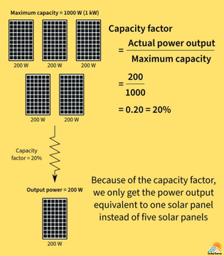
Solar capacity factor

The solar capacity factor is a measure of how effectively a solar power system generates electricity compared to its maximum potential output.
It is calculated as the ratio of the actual electricity produced by a solar power plant over a specific period of time (typically a year) to the amount of electricity it would have produced if it were operating at full capacity the entire time.

Mathematically, it can be expressed as:
A higher capacity factor means the system is producing more power relative to its theoretical maximum. Factors affecting the capacity factor of solar energy include:

• Geographic location (more sunlight = higher capacity factor)

• Weather conditions (cloud cover, rain, etc.)

• Time of year (day length, seasonal variations)

• Efficiency of the solar panels

Typically, solar capacity factors range between 15% and 25% for most locations, although it can be higher in areas with consistent sunlight. For comparison, fossil fuel plants usually have capacity factors around 60%-80%.

Friday, 15 November 2024

Protection circuit diagram explained

This image is a schematic diagram or circuit diagram of an electronic circuit. Let me explain the different components and their functionality based on the symbols used:
1. CB (Circuit Breaker):
   - The circuit breaker symbol represents a device that interrupts the flow of current in the circuit when it exceeds a certain threshold, protecting the circuit from overcurrent or short-circuit conditions.

2. CT (Current Transformer):
   - The current transformer symbol indicates a device used to measure the current in the circuit and provide a scaled-down representation of the current to other components.

3. R (Resistor):
   - The resistor symbol represents a passive electronic component that is used to control or limit the flow of current in the circuit.

4. BF (Breaker Failure):
   - The breaker failure symbol suggests that there is some mechanism or logic to detect the failure of the circuit breaker (CB) and take appropriate action.

5. T (Trip Signal):
   - The trip signal symbol indicates that there is a signal or trigger that can be used to open or interrupt the circuit, likely originating from the breaker failure (BF) detection.

Based on the arrangement and connections between these components, this diagram appears to represent a protective relaying or circuit breaker control system, where the current transformer (CT) monitors the current, and the circuit breaker (CB) can be tripped in the event of a fault or overcurrent condition, with the breaker failure (BF) logic providing additional protection.

This type of diagram is commonly found in electrical power systems, industrial automation, or other engineering domains where reliable circuit protection is essential.

Wednesday, 13 November 2024

Servo Motor

A servo motor is a type of motor that is used in applications where precise control of angular position, velocity, and acceleration is required. Unlike regular motors, a servo motor is part of a closed-loop system, meaning it can receive feedback on its position and adjust accordingly. Here's how it works:

Key Components:

1. DC Motor: The actual motor that drives the movement.
2. Feedback Device: Typically an encoder or potentiometer, this device continuously monitors the motor's position.
3. Controller: A circuit or microcontroller that processes the feedback and adjusts the motor's speed or direction.
4. Gearbox: Often used to increase torque or reduce speed, making the servo motor more powerful in applications requiring precise movement.

How It Works:
1. Input Signal: The controller receives an input signal, usually a pulse-width modulation (PWM) signal, which specifies the desired position of the servo.
2. Positioning: The controller compares the desired position (from the input signal) with the current position (from the feedback device). If there is a difference, it sends a signal to the motor to move in the required direction.
3. Movement: The motor rotates, and the feedback device continuously checks the motor's position. Once the desired position is reached, the controller stops the motor or adjusts it if necessary.
4. Closed-Loop Control: If the servo moves out of position due to external forces or errors, the feedback system detects the discrepancy and corrects it, allowing precise control.

In short, a servo motor is designed to move to a specific position and maintain that position precisely by constantly adjusting based on feedback from its own position sensor.


Tuesday, 12 November 2024

Magnetic Voltage Transformer

A voltage transformer (VT), also known as a potential transformer (PT), is an electrical device used to step down or step up the voltage level in an AC (alternating current) electrical system. It is designed to safely measure and control high voltage by reducing it to a lower, more manageable level. This allows measurement devices (such as voltmeters) or protection relays to operate with safe voltage values, even when the primary system operates at very high voltages.
Key Functions of Voltage Transformers:
1. Voltage Scaling: VTs convert high voltage to a lower, proportional voltage that can be measured safely and accurately. For instance, if the primary voltage is 11 kV, the VT might step it down to 110 V for measurement.

2. Isolation: It electrically isolates the measurement or control devices from the high-voltage circuit, providing protection against electrical shock and equipment damage.

3. Accuracy: VTs are designed to provide precise and stable voltage transformation, making them essential for accurate voltage measurement and monitoring in power systems.

Construction:
Voltage transformers typically consist of:

• Primary winding: Connected to the high-voltage circuit.

• Secondary winding: Provides the scaled-down voltage for measurement or relay protection.

• Core: Usually made of laminated silicon steel to minimize energy losses due to eddy currents.

Applications:
• Metering: Used in power distribution systems for accurate voltage measurement.

• Protection: VTs are also used in relay circuits to detect faults or abnormal voltage conditions.

•System Monitoring: Helps in real-time monitoring of the electrical network's voltage levels.

In summary, a voltage transformer is an essential component for safely managing high voltage systems, allowing for measurement, protection, and control at a manageable level.