Friday, 15 November 2024

Protection circuit diagram explained

This image is a schematic diagram or circuit diagram of an electronic circuit. Let me explain the different components and their functionality based on the symbols used:
1. CB (Circuit Breaker):
   - The circuit breaker symbol represents a device that interrupts the flow of current in the circuit when it exceeds a certain threshold, protecting the circuit from overcurrent or short-circuit conditions.

2. CT (Current Transformer):
   - The current transformer symbol indicates a device used to measure the current in the circuit and provide a scaled-down representation of the current to other components.

3. R (Resistor):
   - The resistor symbol represents a passive electronic component that is used to control or limit the flow of current in the circuit.

4. BF (Breaker Failure):
   - The breaker failure symbol suggests that there is some mechanism or logic to detect the failure of the circuit breaker (CB) and take appropriate action.

5. T (Trip Signal):
   - The trip signal symbol indicates that there is a signal or trigger that can be used to open or interrupt the circuit, likely originating from the breaker failure (BF) detection.

Based on the arrangement and connections between these components, this diagram appears to represent a protective relaying or circuit breaker control system, where the current transformer (CT) monitors the current, and the circuit breaker (CB) can be tripped in the event of a fault or overcurrent condition, with the breaker failure (BF) logic providing additional protection.

This type of diagram is commonly found in electrical power systems, industrial automation, or other engineering domains where reliable circuit protection is essential.

Wednesday, 13 November 2024

Servo Motor

A servo motor is a type of motor that is used in applications where precise control of angular position, velocity, and acceleration is required. Unlike regular motors, a servo motor is part of a closed-loop system, meaning it can receive feedback on its position and adjust accordingly. Here's how it works:

Key Components:

1. DC Motor: The actual motor that drives the movement.
2. Feedback Device: Typically an encoder or potentiometer, this device continuously monitors the motor's position.
3. Controller: A circuit or microcontroller that processes the feedback and adjusts the motor's speed or direction.
4. Gearbox: Often used to increase torque or reduce speed, making the servo motor more powerful in applications requiring precise movement.

How It Works:
1. Input Signal: The controller receives an input signal, usually a pulse-width modulation (PWM) signal, which specifies the desired position of the servo.
2. Positioning: The controller compares the desired position (from the input signal) with the current position (from the feedback device). If there is a difference, it sends a signal to the motor to move in the required direction.
3. Movement: The motor rotates, and the feedback device continuously checks the motor's position. Once the desired position is reached, the controller stops the motor or adjusts it if necessary.
4. Closed-Loop Control: If the servo moves out of position due to external forces or errors, the feedback system detects the discrepancy and corrects it, allowing precise control.

In short, a servo motor is designed to move to a specific position and maintain that position precisely by constantly adjusting based on feedback from its own position sensor.


Tuesday, 12 November 2024

Magnetic Voltage Transformer

A voltage transformer (VT), also known as a potential transformer (PT), is an electrical device used to step down or step up the voltage level in an AC (alternating current) electrical system. It is designed to safely measure and control high voltage by reducing it to a lower, more manageable level. This allows measurement devices (such as voltmeters) or protection relays to operate with safe voltage values, even when the primary system operates at very high voltages.
Key Functions of Voltage Transformers:
1. Voltage Scaling: VTs convert high voltage to a lower, proportional voltage that can be measured safely and accurately. For instance, if the primary voltage is 11 kV, the VT might step it down to 110 V for measurement.

2. Isolation: It electrically isolates the measurement or control devices from the high-voltage circuit, providing protection against electrical shock and equipment damage.

3. Accuracy: VTs are designed to provide precise and stable voltage transformation, making them essential for accurate voltage measurement and monitoring in power systems.

Construction:
Voltage transformers typically consist of:

• Primary winding: Connected to the high-voltage circuit.

• Secondary winding: Provides the scaled-down voltage for measurement or relay protection.

• Core: Usually made of laminated silicon steel to minimize energy losses due to eddy currents.

Applications:
• Metering: Used in power distribution systems for accurate voltage measurement.

• Protection: VTs are also used in relay circuits to detect faults or abnormal voltage conditions.

•System Monitoring: Helps in real-time monitoring of the electrical network's voltage levels.

In summary, a voltage transformer is an essential component for safely managing high voltage systems, allowing for measurement, protection, and control at a manageable level.


Monday, 11 November 2024

TDA2030 10W Amplifier working principle and connection

This schematic diagram shows the circuit for a 10W audio amplifier using the TDA2030 integrated circuit. The TDA2030 is a popular audio power amplifier chip that can provide up to 10 watts of power output. Let's go through the working principle and connections of this circuit:
1. Input Signal:
   - The audio input signal is connected to the "Audio in" terminal, which is then fed into the TDA2030 amplifier chip.

2. Power Supply:
   - The circuit is powered by a 12VDC power source, which is connected to the positive and negative terminals of the TDA2030.

3. Feedback and Biasing:
   - The 10K resistor and 100 Ohm resistor form a feedback network that sets the gain and biasing for the TDA2030 amplifier.
   - The 10uF capacitor provides decoupling and stabilization for the power supply.

4. Speaker Connection:
   - The output of the TDA2030 is connected to a speaker, which is the final load for the amplifier.

5. Tip 3055 Transistors:
   - The two Tip 3055 transistors are used as output devices to handle the high current required to drive the speaker.
   - They are connected in a push-pull configuration to amplify the signal from the TDA2030 and deliver the necessary power to the speaker.

The working principle is as follows:
- The audio input signal is amplified by the TDA2030 integrated circuit.
- The feedback network sets the gain and biasing for the amplifier.
- The Tip 3055 transistors act as the output stage, providing the necessary power to drive the connected speaker.
- The entire circuit is powered by the 12VDC power source, which supplies the required voltage and current for the operation of the amplifier.

This is a basic yet effective audio amplifier circuit that can be used in various audio applications, such as speakers, headphones, or other audio equipment, where a 10-watt output power is required.

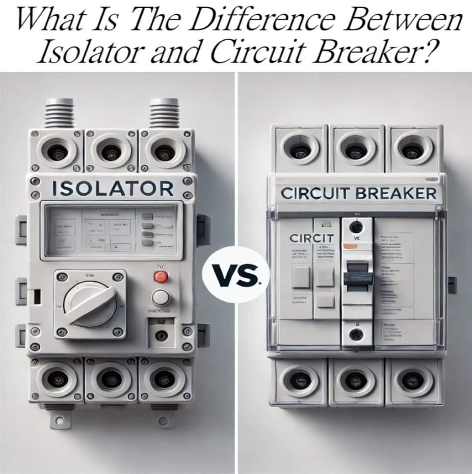
What is the difference between isolator and circuit breaker?

The primary difference between an isolator and a circuit breaker lies in their functions and operation:
1. Isolator:

Function: An isolator is a mechanical switch used to ensure that a circuit is completely disconnected from the power supply for maintenance or safety purposes. It is used primarily in the "off" state and operates only when there is no current flowing through the circuit.

Operation: It is a manual switch and does not interrupt current flow under fault conditions. It is typically used in conjunction with a circuit breaker.

Location: It is often installed on the outgoing side of a circuit breaker to isolate parts of the system for maintenance or repair.

Safety: Provides safety by ensuring that the circuit is fully de-energized before work begins.

2. Circuit Breaker:

Function: A circuit breaker is an automatic switch that is designed to protect the electrical circuit from damage caused by overcurrent, short circuits, or other fault conditions. It automatically interrupts the current flow when it detects a fault.

Operation: It can interrupt current flow while the system is under load, and it works automatically without human intervention.

Location: It is installed in the power distribution system to protect electrical equipment from overload or faults.

Safety: Provides protection by automatically breaking the circuit during fault conditions (like overloads or short circuits) to prevent damage.

In summary, an isolator is for safely disconnecting a circuit when no current is flowing, while a circuit breaker automatically cuts off the current in case of an electrical fault to protect the system.

Saturday, 9 November 2024

Can neutral wire cause electric shock?

Yes, a neutral wire can cause electric shock under certain conditions, although it is generally considered safer than live (hot) wires. Here’s Why:
Explanation:

1. Function of Neutral Wire:
   - The neutral wire is part of an electrical system designed to carry current away from devices back to the electrical panel, completing the circuit. It is typically at ground potential.

2. Conditions Leading to Shock:
   - Faulty Wiring: If there is a fault in the wiring or if the neutral wire becomes disconnected, it can carry current instead of being at ground potential.
   - Voltage Imbalance: If there is an issue with the electrical supply, such as a voltage imbalance, the neutral wire can become energized, posing a shock hazard.
   - Faulty Appliances: If an appliance has a fault that allows current to leak to the neutral wire, touching the neutral wire could result in an electric shock.

Example:

Imagine a situation where an appliance with a damaged insulation is plugged into an electrical outlet. If the live wire contacts the metal casing of the appliance, the neutral wire may carry some current due to the faulty connection. If a person touches the neutral wire while standing on a wet floor, they may complete the circuit to ground and receive an electric shock.

Conclusion:

While the neutral wire is designed to be safe, it can become dangerous if there are faults or imbalances in the electrical system. Safety precautions, such as proper wiring and regular maintenance, are essential to prevent such hazards.

Sunday, 3 November 2024

On-Grid solar system for home

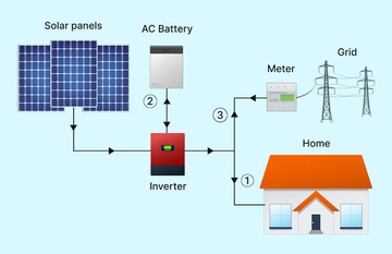
This image depicts a solar power system for a home. The key components and their functions are:
1. Solar Panels: These convert sunlight into electrical energy that can be used to power the home.

2. AC Battery: This battery stores the electrical energy generated by the solar panels, allowing the home to use the power even when the sun is not shining.

3. Inverter: This device converts the direct current (DC) electricity generated by the solar panels into alternating current (AC) that can be used to power the home's electrical systems.

4. Grid Meter: This measures the flow of electricity between the home's solar power system and the main electrical grid. If the home generates more electricity than it uses, the excess can be sold back to the grid.

5. Home: The solar power system is designed to provide electricity to power the entire home, reducing or eliminating the need for grid-supplied electricity.

This integrated system allows the homeowner to generate their own renewable energy from the sun, reduce their reliance on the main electrical grid, and potentially even earn money by selling excess electricity back to the grid.