Tuesday 27 June 2023

Common problems of an inverter

The inverter is a critical component of a solar power system that converts the DC power generated by the solar panels into AC power that can be used to power household loads or fed back into the grid. If the inverter is not functioning properly, it can significantly impact the performance and efficiency of the entire solar power system. Here are some signs that your inverter may need to be replaced:
1. Low or No Power Output: If your solar power system is not generating as much power as it should, or if there is no power output at all, it could be a sign that the inverter is not functioning properly.

2. Error Messages or Warning Lights: Some inverters have built-in error messages or warning lights that indicate when there is a problem. If you see an error message or warning light, it could be a sign that the inverter needs to be replaced.

3. Overheating: If the inverter is getting too hot, it may shut down automatically or reduce its power output. Overheating can be caused by a variety of factors, including poor ventilation or a malfunctioning cooling system.

4. Unusual Noises: If you hear unusual noises coming from the inverter, such as buzzing or humming, it could be a sign of a problem. This could be caused by a faulty fan or other internal component.

5. Age: Inverters typically have a lifespan of 10 to 15 years. If your inverter is approaching or exceeding this age, it may be time to consider replacing it.
If you notice any of these signs, it is important to consult with experienced solar power professionals to diagnose the problem and determine whether the inverter needs to be replaced. In some cases, it may be possible to repair the inverter rather than replacing it, but in other cases, replacement may be the best option to ensure the continued performance and efficiency of your solar power system.

Safety considerations in a MV network work

Safety is a critical consideration for any medium voltage (MV) network, as high voltages can pose a serious risk of electrical shock and other hazards. Some key safety considerations for an MV network include:
1. Personal Protective Equipment (PPE): Workers who are involved in the installation, maintenance, or repair of an MV network should be provided with appropriate personal protective equipment, such as insulated gloves, safety glasses, and flame-resistant clothing.

2. Lockout/Tagout Procedures: Lockout/tagout procedures should be implemented to prevent unexpected energization of equipment while workers are performing maintenance or repair work.

3. Grounding and Bonding: All equipment in the MV network should be properly grounded and bonded to prevent electrical shock and other hazards.

4. Warning Signs and Labels: Warning signs and labels should be placed on equipment and in areas where high voltages are present to warn workers and others of the potential hazards.

5. Electrical Clearances: Minimum electrical clearances should be maintained between equipment and other objects to prevent arcing and other hazards.

6. Safety Interlocks: Safety interlocks, such as door switches and pressure switches, should be installed on equipment to prevent operating equipment while doors are open or pressure is not within the safe range.

7. Proper Equipment Selection: All equipment used in the MV network should be designed and tested to meet appropriate safety standards and should be installed and used in accordance with manufacturer instructions.

8. Training and Education: Workers who are involved in the installation, maintenance, or repair of an MV network should be provided with appropriate training and education on safe work practices and procedures.
It is important to consult with experienced electrical engineers and other professionals to ensure that all necessary safety considerations are taken into account when designing, installing, and maintaining an MV network.

Sunday 25 June 2023

Protection Zone

A protection zone is an area of an electrical system that is protected by a specific set of protective devices. The boundaries of a protection zone are typically defined by the location of the protective devices and the type of protection that they provide.
The purpose of protection zones is to ensure that a fault in one area of an electrical system does not cause damage to other areas of the system. For example, if a fault occurs in a transformer, the protective devices in the protection zone around the transformer will trip the circuit breaker, isolating the fault and preventing it from spreading to other parts of the system.

Protection zones are an important part of the design of any electrical system. They help to ensure the safety and reliability of the system by preventing the spread of faults.

Here are some of the benefits of using protection zones:

1. They can help to prevent the spread of faults.

2. They can help to protect equipment from damage.

3. They can help to improve the reliability of the electrical system.

4. They can help to reduce the risk of injury to personnel.

Here are some of the challenges of using protection zones:

1. They can be expensive to implement.

2. They can be difficult to design and install.

3. They can require regular maintenance.

Overall, protection zones are an important part of the design of any electrical system. They can help to improve the safety, reliability, and efficiency of the system.

Saturday 24 June 2023

World's largest electric grid

The world's largest electric grid is the **North American Interconnection** (NAI), which spans the contiguous United States, Canada, and parts of Mexico. It is a vast network of power lines, substations, and other equipment that delivers electricity to over 400 million people. The NAI is operated by a number of different organizations, but it is essentially one large interconnected system.
The NAI is the largest in terms of both geographic coverage and total generating capacity. It has a peak load of over 1.2 trillion watts, which is more than the combined peak loads of the next four largest grids. The NAI is also one of the most reliable grids in the world, with a very low average outage rate.
Other large electric grids include:

* The Continental European Grid (ENTSO-E)
* The Eastern Interconnection (EI)
* The Western Interconnection (WI)
* The South American Power System Interconnection (SIP)
* The Indian Inter-State Power Grid (IIP)
These grids are all interconnected to some extent, which allows electricity to flow between different countries and regions. This helps to ensure that there is always enough electricity to meet demand, even during times of peak load.

Wednesday 21 June 2023

Design of a 5KW solar electric system

A basic design for a 5 kW solar power system to power a house with a 3 kW load using 300 W solar panels. Here's an overview of the components you will need:
1. Solar Panels: 
To achieve the required 5 kW power output, you will need a total of 17 solar panels. Since each panel has a power output of 300 W, the total power output of the panels will be 17 x 300 W = 5.1 kW.
2. Solar Inverter: 
A solar inverter is required to convert the direct current (DC) power generated by the solar panels into alternating current (AC) power that can be used to power the household loads. For a 5 kW solar power system, a grid-tied inverter with a capacity of at least 5 kW would be suitable.
3. Mounting Structure: 
The solar panels will need to be mounted on a suitable structure, such as a rooftop or ground-mounted structure, to ensure they are oriented towards the sun and are secure.
4. Electrical Cables: 
You will need electrical cables to connect the solar panels to the inverter and to connect the inverter to the household loads. The size and type of cables required will depend on factors such as the length of the cable run and the current carrying capacity required.
5. DC Disconnect: 
A DC disconnect switch is required to isolate the solar panels from the inverter for maintenance or repair work.

6. AC Breaker Panel: 
An AC breaker panel is required to distribute the AC power generated by the inverter to the household loads. It should be sized to handle the maximum expected load of 3 kW.

7. Monitoring System: 
A monitoring system is recommended to track the performance of the solar power system and identify any issues that may arise.
Keep in mind that this is a basic design and the specific requirements for your solar power system may vary depending on factors such as the location, climate, and orientation of the solar panels. It is important to consult with experienced solar power professionals to ensure that the design is appropriate for your specific needs.

Saturday 10 June 2023

Design of a 20KV MV Network

Design of a 20KV MV Network

Steps involved in designing a 20KV MV network.
1. Load Calculation: The first step is to determine the load requirements of the network. This involves estimating the amount of power that will be consumed by the various loads connected to the network, such as motors, lighting, and other equipment.

2. Cable Sizing: Once the load requirements are known, the size of the cables needed to carry the required current can be determined. This will depend on factors such as the distance of the network, the type of cable used, and the voltage drop allowed.

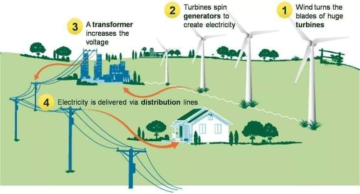
3. Equipment Selection: Next, you will need to select the necessary equipment for the network. This will include transformers, switchgear, circuit breakers, and other components needed to distribute power and protect the network.

4. Voltage Drop Calculation: Voltage drop is the reduction in voltage that occurs as electricity flows through a cable. It is important to calculate the voltage drop to ensure that the network operates properly and efficiently. The voltage drop calculation will depend on the length of the cable, the size of the cable, and the load on the network.

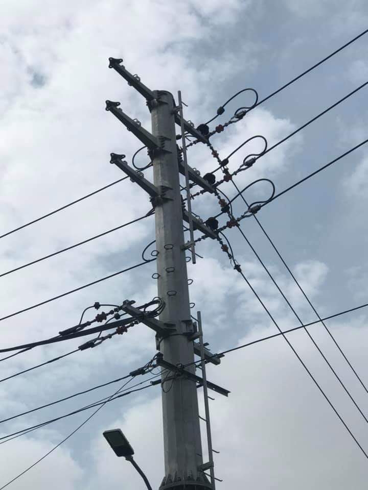
5. Mechanical Materials: In addition to electrical materials, you will also need to consider mechanical materials such as poles, supports, and other hardware needed to install and maintain the network.

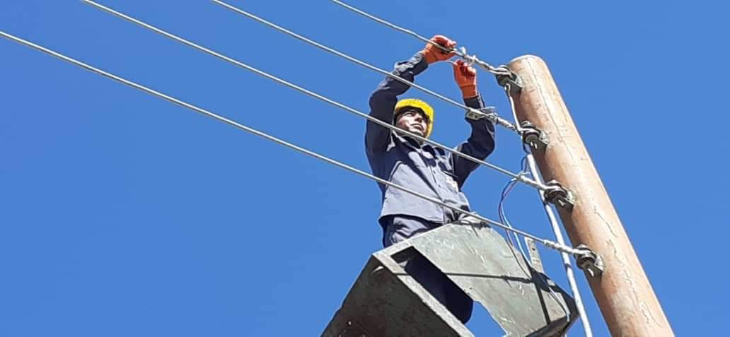
6. Safety Considerations: Finally, it is important to consider safety when designing an MV network. This includes selecting equipment that meets safety standards, ensuring proper grounding, and designing the network to minimize the risk of electric shock and other hazards.

Keep in mind that designing an MV network is a complex process that requires specialized knowledge and expertise.
The most common types of cables used in medium voltage (MV) networks are:

1. XLPE (Cross-Linked Polyethylene) Cables: XLPE cables are widely used in MV networks due to their high dielectric strength, resistance to moisture and chemicals, and good thermal properties. They are suitable for both underground and overhead installations.

2. EPR (Ethylene Propylene Rubber) Cables: EPR cables are also commonly used in MV networks. They have good electrical properties, are resistant to environmental factors such as moisture and UV radiation, and have good mechanical strength.

3. PILC (Paper-Insulated Lead-Covered) Cables: PILC cables were widely used in the past, but are now being phased out due to their relatively low electrical performance and susceptibility to moisture and other environmental factors. However, some older MV networks may still use PILC cables.

4. MI (Mineral-Insulated) Cables: MI cables have a copper conductor insulated with mineral insulation and are enclosed in a copper sheath. They are highly resistant to fire and have good mechanical strength, making them suitable for high-risk applications.

The choice of cable type will depend on factors such as the specific application, environmental conditions, and installation requirements. It is important to consult with electrical engineers and other professionals to ensure the appropriate cable type is selected for a given MV network.

Monday 5 June 2023

Top 10 electrical projects

Top 10 electrical projects that you can try:

1. **LED Flasher:** 
This is a simple project that will teach you how to use LEDs and resistors. You can use a breadboard to build the circuit, and you will need a few basic tools, such as a soldering iron and wire strippers.
2. **Light Sensor:** 
This project will teach you how to use a light sensor. You can use the sensor to control a LED, or you can use it to create a security system that turns on a light when someone enters a room.
3. **Temperature Monitor:** 
This project will teach you how to use a temperature sensor. You can use the sensor to display the temperature on a LCD screen, or you can use it to control a heating or cooling system.
4. **Motion Sensor:** 
This project will teach you how to use a motion sensor. You can use the sensor to turn on a light, or you can use it to trigger an alarm.
5. **Sound Sensor:** 
This project will teach you how to use a sound sensor. You can use the sensor to turn on a light when you clap your hands, or you can create a security system that turns on an alarm when someone makes a loud noise.
6. **Home Automation System:** 
This project will teach you how to use a microcontroller to control various devices in your home, such as lights, thermostats, and door locks.
7. **Robotic Arm:** 
This project will teach you how to use a microcontroller to control a robotic arm. You can use the arm to pick up objects, move them around, and even paint pictures.
8. **Solar-Powered Car:** 
This project will teach you how to use solar cells to power a car. You can use the car to race against your friends, or you can use it to learn about the principles of solar energy.
9. **Wind Turbine:** 
This project will teach you how to use wind energy to generate electricity. You can use the turbine to power a light bulb, or you can use it to learn about the principles of wind energy.
10. **Electric Vehicle Charger:** 
This project will teach you how to build an electric vehicle charger. You can use the charger to charge your electric car, or you can use it to learn about the principles of electric vehicle charging.

These are just a few ideas to get you started. There are many other electrical projects that you can try. With a little research, you can find a project that interests you and that is within your skill level.

AC 12V-0-12V transformer