Sunday, 19 January 2025

What are types of electrical switches?

Types of electrical switches: 
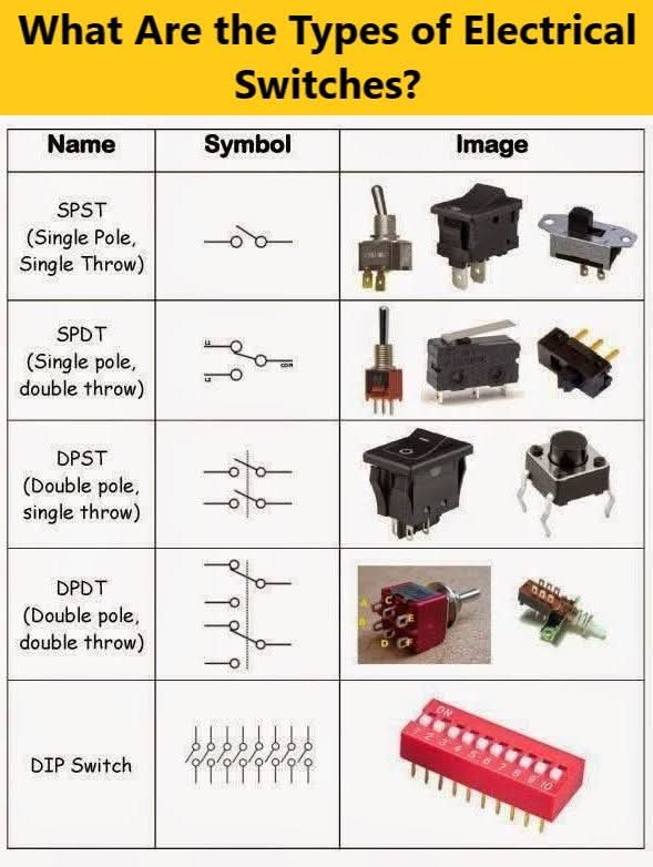
SPST (Single Pole, Single Throw):
• Symbol: A simple switch with one input and one output.
• Function: This switch connects or disconnects a single circuit. It's like a basic on/off switch.
• Image: Shows various forms of SPST switches, including toggle, rocker, and slide switches.

SPDT (Single Pole, Double Throw):
• Symbol: A switch with one input and two outputs.
• Function: This switch can connect the input to one of two different outputs, allowing for switching between two different circuits or states. It's commonly used for switching between two different power sources or for changeover functions.
• Image: Depicts toggle, slide, and push-button SPDT switches.

DPST (Double Pole, Single Throw):
• Symbol: Two SPST switches in parallel, each controlling a separate circuit.
• Function: This switch controls two separate circuits simultaneously, essentially like having two SPST switches operated by a single mechanism.
• Image: Shows examples like a rocker switch and a push-button switch.

DPDT (Double Pole, Double Throw):
• Symbol: Two SPDT switches in parallel.
• Function: This switch can control two circuits and switch each between two different states. It's often used in applications where you need to control the direction of current flow in two circuits, like in reversible motors or complex switching systems.
• Image: Features rotary switches and toggle switches.

DIP Switch (Dual In-line Package Switch):
• Symbol: A series of small switches arranged in a row.
• Function: DIP switches are used for customizing the behavior of an electronic device. Each switch in the package can be set to on or off, typically used in settings or configuration of electronic circuits.
• Image: Shows a DIP switch with multiple toggle switches.

Push-Button Switch:
• Symbol: Typically shown as a circle or rectangle with a line through it indicating the button.
• Function: This switch is activated by pressing a button. It can be momentary (returns to its original state when released) or maintained (stays in the new state until pressed again). They are commonly used in applications like doorbells, start/stop buttons, or reset buttons.
• Image: Typically looks like a button you press.

Saturday, 18 January 2025

What happens when you touch an electrical busbar?

When you touch an electrical busbar, especially one that is live or energized, you risk severe electrical shock or electrocution.
Here's why:
- Electrical Conductivity: Busbars are designed to conduct electricity efficiently. They are typically made from materials like copper or aluminum, which are excellent conductors.

- High Voltage/Current: Busbars are used to distribute power in electrical systems, often carrying high voltage or current.
Touching one without proper protection can lead to immediate and severe injury or death.

- No Insulation: The busbars in the image are not insulated, which means there is no protective layer to prevent direct contact with the electricity.

- Safety Measures: Always ensure that electrical work involving busbars is done with the power turned off, and use proper personal protective equipment (PPE) like insulated gloves and tools.

In summary, touching an electrical busbar without safety precautions can be extremely dangerous. Always follow safety protocols when dealing with electrical systems.

Friday, 17 January 2025

What is the difference between over current, overload and over voltage?

What's the difference between overcurrent, overload, and overvoltage.
Overcurrent (O/C):
1. Definition: Overcurrent refers to a situation where the current flowing through a circuit exceeds the rated current of the equipment or the conductor.
2. Causes: This can be due to short circuits, ground faults, or excessive load.
3. Protection: Overcurrent protection devices like fuses or circuit breakers are used to interrupt the circuit to prevent damage. These devices are designed to trip or blow when the current exceeds a certain threshold.
Overload (O/L):
1. Definition: Overload occurs when the current drawn by the equipment exceeds its rated capacity but does not necessarily exceed the capacity of the electrical system.
2. Causes: This is typically due to excessive load being applied to the equipment, such as too many devices drawing power from a single circuit.
3. Protection: Overload protection is often provided by thermal devices or electronic circuits that detect prolonged overcurrent conditions and disconnect the circuit to prevent overheating and potential damage.
Overvoltage (O/V):
1. Definition: Overvoltage is when the voltage in a circuit exceeds the design voltage of the equipment or system.
2. Causes: This can be due to power surges, lightning strikes, switching operations, or faults in the power supply.
3. Protection: Overvoltage protection devices like surge protectors, voltage suppressors, or transient voltage surge suppressors (TVSS) are used to clamp the voltage to safe levels or divert excess voltage to ground.

In summary, while all three conditions involve excessive electrical parameters, they differ in what is excessive:
Overcurrent deals with excessive current flow.
Overload deals with equipment drawing more current than it's designed for, but within the system's capacity.
Overvoltage deals with excessive voltage levels.

Each condition has its specific protective measures to ensure the safety and longevity of electrical systems and equipment.

Sunday, 12 January 2025

A single-phase motor controlled by a contactor and a pressure switch

A single-phase motor controlled by a contactor and a pressure switch.
This type of setup is commonly used for applications like air compressors, water pumps, and other equipment that needs to be automatically turned on and off based on pressure.

Key Components:

▪️ Incoming Power Supply: This is the main power source (single-phase AC).
▪️ Contactor (Black Box): An electrically controlled switch used for switching a power circuit on or off. It consists of a coil (electromagnet) and contacts. When the coil is energized, the contacts close, allowing current to flow to the motor.
▪️ Pressure Switch (White Box): A switch that opens and closes based on the pressure in a system (e.g., air pressure in a compressor tank). It controls the contactor's coil.
▪️ Motor: The single-phase motor that needs to be controlled.
▪️ Wiring: The lines connecting the components represent the electrical wires.

Wiring and Functionality:

1. Main Power to Contactor: The incoming power supply is connected to the main contacts of the contactor.

2. Contactor to Motor: The output of the contactor is connected to the motor. When the contactor's contacts are closed, power flows to the motor, and it runs.

3. Pressure Switch to Contactor Coil: The pressure switch is connected to the coil of the contactor. This is the control circuit.

4. Pressure Switch Operation:
    ▪️ When the pressure in the system is below a certain setpoint, the pressure switch *closes* its contacts. This completes the circuit to the contactor coil, energizing it.
    ▪️ When the contactor coil is energized, it closes the main contacts, sending power to the motor and turning it on.
    ▪️ As the motor runs, it increases the pressure in the system. When the pressure reaches a higher setpoint, the pressure switch *opens* its contacts.
    ▪️ Opening the pressure switch contacts de-energizes the contactor coil, causing the main contacts to open and stopping power to the motor.

How it Works (Example with an Air Compressor):
Imagine this is for an air compressor.

1. The compressor starts, and the pressure in the tank begins to rise.
2. When the pressure reaches the "cut-out" pressure (the higher setpoint), the pressure switch opens, turning off the compressor motor.
3. As air is used from the tank, the pressure drops.
4. When the pressure reaches the "cut-in" pressure (the lower setpoint), the pressure switch closes, turning the compressor motor back on to refill the tank.

Safety Considerations:

▪️ Qualified Electrician: Working with electrical wiring can be dangerous. It is strongly recommended to have this type of wiring done by a qualified electrician.
▪️ Proper Grounding: Ensure all components are properly grounded for safety.
▪️ Correct Wiring: Incorrect wiring can lead to damage to equipment or electrical hazards.

Saturday, 11 January 2025

How can you find that a motor is AC or DC without any aid?

How can you find that a motor is AC or DC without any aid?

AC motor : 
1. There are 6 terminals of the AC motor with all equal sizes.
2. There are cooling strips in the AC motor.
3. The cooling fan is outside of the AC Motor.

DC motor 
1. DC Compound Motors also has 6 terminals but 4 of them are of the same size and 2 of the terminals are always smaller than the other four.
2. There are no cooling strips in DC Motor.
3. The cooling fan is inside the DC Motors.

- Synchronous motors have 5 terminals of which 3 of them are used to connect three phases (AC) and 2 of them are for rotor excitation and provided with DC supply.

- If a motor has 4 terminals then it will lie in the
category of DC Motors.

- If a motor has 3 terminals then it will bea
Y-connected AC Motor and its windings are connected in star internally.

-If a motor has 2 terminals then it will bea
single-phase induction motor

Saturday, 4 January 2025

Electrical Grid Components and Voltage Transformations

Electrical Grid Components and Voltage Transformations
The Electrical Grid, consists of:

• Power Plants: Where electricity is generated.
Substation Power Transformers: Where voltage is stepped up for transmission.
• Distribution Transformers: Where voltage is stepped down for distribution.

The purpose of increasing voltage is to reduce transmission losses. Today, we'll discuss electrical losses within the grid.

As shown in the attached image, a power plant generates at 11 kV with 54.5 Amperes. This voltage isn't suitable for long-distance transmission, hence it's increased using a Step-Up Transformer.

The voltage is raised to 66 kV, 132 kV, 220 kV, 400 kV, or 500 kV. Higher voltage means less current for the same power, reducing the conductor cross-sectional area needed, which in turn lowers the cost of building transmission lines, whether they are overhead (OHTL) or underground (UGC).

Also, less energy is lost in this process:

Power Losses = I² x R
In the image, the voltage is raised to 500 kV with a current of 1 Ampere.

Electricity Transmission:
Electricity is transmitted from power plants through overhead (OHTL) or underground cables (UGC) to transformer stations. Here, voltage is reduced with Step-Down Transformers:

• From 500 kV to 220 kV with 2.27 Amperes.
• Then from 220 kV to 66 kV with 7.58 Amperes.
• Further reduced to 22 kV (medium voltage) with 22.7 Amperes.
• Then to 11 kV with 45.4 Amperes.

Finally, Distribution Transformers reduce it to 415 V for industrial and small workshops, and 230 V for residential (Phase to Earth).

This explanation is simplified for the electrical grid in Austria, but the concept is universal.
The colors used in the explanation:

• Red: Power generation.
• Blue: Transformer stations.
• Green: Distribution transformers.
• Black: Consumers (residences, commercial centers, hospitals, etc.).

It's crucial to understand that ideally, input power (Pin) should equal output power (Pout). However, in reality, there are losses in the grid. No power grid in the world operates without losses, which can range from 2% to 6% in a well-maintained grid.

These losses are:
- Technical losses: Due to aging equipment, lack of maintenance, not using capacitors or reactive power compensators, and not employing modern measuring devices to identify grid faults.
- Commercial losses: Occur from illegal connections bypassing meters, theft in informal markets, etc.

This provides a basic overview of how electrical grids operate and manage power losses.

Friday, 3 January 2025

5KW Hybrid Solar System


To explain the connection, operation modes, and capacity of each component for a 5kW hybrid solar system, let's break down the image:

Components and Their Capacities:
1. Solar Panels:
• Capacity: Assuming a total of 5kW peak power.
• Details: Typically, this would involve around 15-20 panels, each with a capacity of 250-350W, depending on the specific model and efficiency.
2. Solar Hybrid Inverter:
• Capacity: 5kW AC output.
• Function: Manages power flow between solar panels, batteries, grid, and loads. It can operate in grid-tied, off-grid, or hybrid mode.
3. Battery Storage:
• Capacity: Assuming a usable storage capacity of around 10-20kWh for a typical home setup.
• Details: This could be achieved with lithium-ion batteries, with each unit having a capacity of 2.5-5kWh.
4. Charge Controller:
• Capacity: Should be compatible with the solar array's output, typically integrated within the hybrid inverter for this setup.
5. AC Distribution:
• Capacity: Handles the AC output from the inverter to the home's electrical system, ensuring a stable 220V AC supply.
6. Grid Connection:
• Function: Allows the system to draw or feed power to/from the grid, depending on the mode of operation.

Operation Modes:
1. Grid-Tied Mode:
• Function: The system is connected to the grid. Excess solar power is fed back into the grid, and when solar production is low, power is drawn from the grid.
2. Off-Grid Mode:
• Function: The system operates independently of the grid. It relies solely on solar power and stored battery energy. If both are insufficient, non-essential loads might be shed.
3. Hybrid Mode:
• Function: This is the most common operation for a hybrid system. It automatically switches between grid-tied and off-grid based on power availability, maximizing solar and battery usage while still having grid support.

Connection Explanation:
- Solar Panels to Inverter: Solar panels are connected in series or parallel to achieve the desired voltage and current for the inverter.
- Inverter to Battery: The inverter manages charging and discharging of the batteries, ensuring they are charged from solar when available and discharged when necessary.
- Inverter to AC Loads: The inverter converts DC from solar panels or batteries to AC for home use, ensuring compatibility with standard home appliances.
- Grid Connection: This allows for selling excess power or buying when needed, managed by the inverter.
- AC Distribution: Ensures that the power from the inverter or grid is distributed correctly throughout the home.

This setup ensures that the system can provide a continuous power supply by optimizing the use of solar energy, battery storage, and grid electricity, making it highly efficient and reliable for a 5kW system.