Wednesday 30 September 2020

How to Design Solar Led Street Light System?

 Solar technology is not a new technology, it was developed in 17th century B.C, and this technology has marked its presence in both developing as well as developed countries. Electric Street lights consume more energy as they use HD lamps. Today we have everything that work with solar energy like solar-powered buildings, vehicles, solar LED street lights, etc., for energy conservation.

Nowadays a new range of solar LED Street lighting make their presence felt everywhere and these lights are environmentally friendly and are easy to install and give high-intensity LED output. The solar LED street lights system convert sun energy to electricity and the system is prompted to turn on as the darkness approaches. Therefore, these lights automatically switch on after the sunset and after sunrise it switches off.

Solar Street Light

Solar Street Light

Design of Solar LED Street Light System

Blockdiagram of Solar LED Street Light

Design of Solar LED Street Light

The solar street lights operate from night until morning. The LED lamp automatically switches on after the sunset and switches off after the sunrise. This system design consists of the following parts:

  • Solar panels
  • LED light
  • Rechargeable battery
  • Controller
  • Pole
  • Interconnecting cables

Solar Panels

In solar street lights, the solar panel is one of the most important parts, and it is also known as solar photovoltaic cell. These cells are of two types: poly crystalline and mono crystalline. Compare to the poly crystalline, mono crystalline conversion rate is higher. Solar panels use light energy from the sun used to convert solar energy into electricity, which can be used to run many applications.

Electrical connections are made in series to accomplish an output voltage and to provide a current facility connections are made in parallel. The majority of modules use silicon or wafer based crystalline silicon but most of these solar panels are inflexible.

LED Light

In modern solar street lights, LEDs are used as lighting source and LED provide much brighter light with lower energy consumption. The energy utilization of LED fixture is lower than the HPS fixture, which is generally used in traditional street lights. Compare to the other HD lamps, and these lights do not emit light in all directions. The directional uniqueness of the LEDs will affect the design of lamps.

The output of the single LEDs is less than the other lamps like compact fluorescent and incandescent lamps but a set of LED lights gives bright light than these two. LED lights offer many benefits like Long life, durability, Eco-friendly and zero UV emissions.

Rechargeable Battery

Rechargeable battery is a type of electrical battery or accumulator and its electro mechanical reactions are reversible so it is called as secondary cell. Usually, there are two types of batteries: lead acid battery and gel cell deep cycle battery.

In solar LED street lights, a battery is used to store electricity from the solar panel during the day time to provide energy in the night time. The capacity and lifetime of the battery is very important as they affect the backup power days of the lights.

Controller

In solar LED street lights, a controller is very important as it usually decides to switch on or switch off the lighting and charging. Some modern controllers are programmable and are used to decide a suitable chance of lighting, dimming and charging. The Controller consists of a battery charger, a secondary power supply, a Led lamp driver, a driver, a protection circuit and a MCU.

The controller also controls the battery from overcharging and under charging conditions. By receiving the power from solar panels it continuously charges the battery in day time and while in evening it supplies the battery power to set of LED street lights.

Pole

For every street light, a strong pole is necessary, especially for a solar street light, there are some components like fixtures, batteries and panels mounted on the top of the pole, and input power consumption is 7.2 watt (LED). In solar street lights, the input operating voltage is 12V DC nominal system voltage, and the light output at the height of 12 feet is min of 09 LUX (unit of luminance).

Interconnecting cables

The battery box, Led light and solar panel are all fixed on the top of the pole and they are interconnected with cables. The cable for this LED system includes a PV module to the controller, and from controller to the battery and lamps. The cable size and lengths depends on the current being carried to the lights and the height of the pole.

With assembling all the above components into a one integrated system results the complete solar LED light system which uses sunlight energy to power the LED lamps fitted on street poles.

Solar LED Street Light Applications

  • Area lighting
  • Airport lighting
  • Hospital parking
  • Parks and playground parking
  • Parking lot lighting
  • Highway road way lighting
  • Street lighting
  • Security light
  • Highway and ramp lighting
  • Bridge lighting
  • Residential lighting
  • Industrial lighting
  • Commercial lighting

LED Lights offers the following Advantages:

  • Require fewer systems for installation.
  • Offers high lighting output when compare to the conventional lights.
  • Requires less time for installation and needs fewer systems.
  • Offers Long shelf life and low maintenance.
  • Offers pollution free ambience.
  • Provides provision of portability.
  • Comes with two year full system warranty.

Disadvantages

  • Initial investment is high when compared to the conventional lights.
  • The dust, snow or moisture can mount up on the PV panels, and thus reduces the energy production.
  • The rechargeable batteries need to be replaced several times.
  • Solar system costs reasonably high, and therefore,, the risk of theft is higher.

This is all about the solar LED Street light and its applications. We hope that you have got clear understanding of this topic, and if you have any doubts on this topic, you can contact to us. And, don’t forget to post your views and feedback on this article in the comment section below.

Saturday 26 September 2020

World’s largest floating solar plant connected in China

 Chinese state-owned developer CECEP has completed a 70MW floating solar project - the largest in the world - at a former coal-mining area of Anhui Province, China, in collaboration with French floating solar specialist Ciel & Terre.

The project, spread across 13 separate islets on an area of 140 hectares, was completed in late 2018, with grid-connection, tests and commissioning carried out this month at the project site in the Lianghuai mining subsidence area, Yongqiao District, Suzhou City.

EPC services were provided by China Energy Conservation Solar Technology and the China Energy Engineering Group Shanxi Electric Power Design Institute. A brand new 18km 110V overhead line was also built for the grid connection of the plant, which is expected to generate up to 77,693MWh of electricity in its first year, equivalent to the power consumption of nearly 21,000 households. 


While the complete facility in Anhui is said to currently be the largest floating PV plant on the same reservoir in the world, nearby, China-based firm Three Gorges New Energy has already partially connected a 150MW floating PV project to the grid, which is likely to become the largest plant globally once fully commissioned.

Equipment

The CECEP system was built using Ciel & Terre's Hydrelio floats, which are locally produced to minimize emissions, optimise logistics costs and offer local employment.

The project uses monocrystalline modules from Chinese manufacturer LONGi Solar, as confirmed by a C&T spokesperson to PV Tech. Central inverters have also been put on stilt platforms on the shoreline of the quarry lake so as not to interfere with neighbouring farm activity. Concrete poles support the electrical installation and 1,500 helical anchors were used for the project and buried at an 8-15 metre-depth to match the water body.

Ciel & Terre has already supplied its floating structure solution to GCL's 32MW FPV plant in Anhui province. It has also recently supplied a 9.8MW PV project featuring rooftop and floating elements in Cambodia.

Sunday 20 September 2020

The source of solar power

The source of solar power

Deep in the center of the sun, intense nuclear activity generates huge amounts of radiation. In turn, this radiation generates light energy called photons. These photons have no physical mass of their own, but carry huge amounts of energy and momentum. Different photons carry different wavelengths of light. Some photons will carry non-visible light (infrared and ultra-violet), whilst others will carry visible light (white light). Over time, these photons push out from the center of the sun. It can take one million years for a photon to push out to the surface from the core. Once they reach the sun’s surface, these photons rush through space at a speed of 670 million miles per hour. They reach earth in around eight minutes. On their journey from the sun to earth, photons can collide with and be deflected by other particles, and are destroyed on contact with anything that can absorb radiation, generating heat. That is why you feel warm on a sunny day: your body is absorbing photons from the sun. Our atmosphere absorbs many of these photons before they reach the surface of the earth. That is one of the two reasons that the sun feels so much hotter in the middle of the day. The sun is overhead and the photons have to travel through a thinner layer of atmosphere to reach us, compared to the end of the day when the sun is setting and the photons have to travel through a much thicker layer of atmosphere.

This is also one of the two reasons why a sunny day in winter is so much colder than a sunny day in summer. In winter, when your location on the earth is tilted away from the sun, the photons have to travel through a much thicker layer of atmosphere to reach us.


(The other reason that the sun is hotter during the middle of the day than at the end is because the intensity of photons is much higher at midday. When the sun is low in the sky, these photons are spread over a greater distance simply by the angle of your location on earth relative to the sun.)


Monday 7 September 2020

DELTA-STAR and Distribution Transformer Unbalanced Loades

 DELTA-STAR and Distribution Transformer Unbalanced Loades

There are two types of unbalanced load. One type can be connected line-to-neutral and the other can be connected line-to-line. Although both unbalances can occur simultaneously during transformer loading, let us consider each separately.

Given a Dyn1 transformer, if a single phase load is connected line-to-neutral, the currents can be shown as follows:

When the load is connected to phase-a and neutral, the resulting load current I will flow in only one of the three transformer secondary windings. On the primary side, the current flow will appear as a line-to-line connected load. Current IA will have the same phase angle as the load current and IC=IA. Thus, a single phase load connected between any phase and neutral on the secondary side will appear as a line-to-line connected load on the primary.

If a single phase load is connected line-to-line, the currents can be shown as follows:

This type of unbalance is a bit more complicated. The load current flows in two of the secondary windings and each will have equal magnitude but opposite phase angle. On the primary side, current will appear in each of the three lines. Line current IA will have twice the magnitude as IB and IC but opposite phase angle. Thus, a single phase load connected line-to-line on the secondary will produce imbalanced line currents on the primary side. Two of the line currents will have equal magnitude and phase angle. One of the line currents will have twice the magnitude and opposite phase angle.

The unbalanced loading of a transformer is typically analyzed using the method of symmetrical components, but the approach shown above might be more intuitive for those not familiar with that method.

Tuesday 1 September 2020

What happens if two single electric meters are connected to two different loads with the same neutral (separated phases and combined neutral)?

What happens if two single electric meters are connected to two different loads with the same neutral (separated phases and combined neutral)?

Here is the conception drawing of the situation. When the neutral of two houses are same but different phases.

Energy Meter:

Energy meters are designed for domestic current ranges of few amperes (10–20) amps depending upon load requirements.

As per your  situation demands, let us understand consequences which will result.

Meter 2 will read its rated load consumption details and there will be no issue regarding meter 2.

Because local circuit for recording power details are met in load 2 circuit itself.

Coming to meter 1, here comes the actual consequence. Meter 1 reads its Load and Load of meter 2 also.

Meter 1 should damage due to large currents flowing in current coil, if current range of meter 1 exceeds. If not meter 1 should continuously read load 2 consumption also.

Current coil of meter 1 observe large current so, meter consumption increases though it is not actually consuming it.

So, consumer 1 should pay for 2 domestic loads, where consumer 2 wont have any issue and he pays for meter 2 only.


Monday 31 August 2020

What happens if a phase and neutral of a single-phase energy meter is reversed?

Installation of protection relays

 Commissioning tests of protection relays at site (before set to work)

Installation of protection relays

Installation of protection relays at site creates a number of possibilities for errors in the implementation of the scheme to occur. Even if the scheme has been thoroughly tested in the factory, wiring to the CTs and VTs on site may be incorrectly carried out, or the CTs/VTs may have been incorrectly installed.

The impact of such errors may range from simply being a nuisance (tripping occurs repeatedly on energisation, requiring investigation to locate and correct the errors) through to failure to trip under fault conditions, leading to major equipment damage, disruption to supplies and potential hazards to personnel.

The strategies available to remove these risks are many, but all involve some kind of testing at site. Commissioning tests at site are therefore invariably performed before protection equipment is set to work. The aims of commissioning tests are:

  1. To ensure that the equipment has not been damaged during transit or installation
  2. To ensure that the installation work has been carried out correctly
  3. To prove the correct functioning of the protection scheme as a whole

The tests carried out will normally vary according to the protection scheme involved, the relay technology used, and the policy of the client. In many cases, the tests actually conducted are determined at the time of commissioning by mutual agreement between the client’s representative and the commissioning team.

The following tests are invariably carried out, since the protection scheme will not function correctly if faults exist.

  • Wiring diagram check, using circuit diagrams showing all the reference numbers of the interconnecting wiring
  • General inspection of the equipment, checking all connections, wires on relays terminals, labels on terminal boards, etc.
  • Insulation resistance measurement of all circuits 
  • Perform relay self-test procedure and external communications checks on digital/numerical relays 
  • Test main current transformers
  • Test main voltage transformers
  • Check that protection relay alarm/trip settings have been entered correctly 
  • Tripping and alarm circuit checks to prove correct functioning
In addition, the following checks may be carried out, depending on the factors noted above (not covered in this technical article):

  • Secondary injection test on each relay to prove operation at one or more setting values
  • Primary injection tests on each relay to prove stability for external faults and to determine the effective current setting for internal faults (essential for some types of electromechanical relays)
  • Testing of protection scheme logic

Insulation resistance tests

All the deliberate earth connections on the wiring to be tested should first be removed, for example earthing links on current transformers, voltage transformers and DC supplies. Some insulation testers generate impulses with peak voltages exceeding 5kV. In these instances any electronic equipment should be disconnected while the external wiring insulation is checked.

The insulation resistance should be measured to earth and between electrically separate circuits. The readings are recorded and compared with subsequent routine tests to check for any deterioration of the insulation.

The insulation resistance measured depends on the amount of wiring involved, its grade, and the site humidity. Generally, if the test is restricted to one cubicle, a reading of several hundred megohms should be obtained. If long lengths of site wiring are involved, the reading could be only a few megohms.

Protection relay self-test procedure

Digital and numerical relays will have a self-test procedure that is detailed in the appropriate relay manual. These tests should be followed to determine if the relay is operating correctly.

This will normally involve checking of the relay watchdog circuit, exercising all digital inputs and outputs and checking that the relay analogue inputs are within calibration by applying a test current or voltage.

For these tests, the relay outputs are normally disconnected from the remainder of the protection scheme, as it is a test carried out to prove correct relay, rather than scheme, operation.

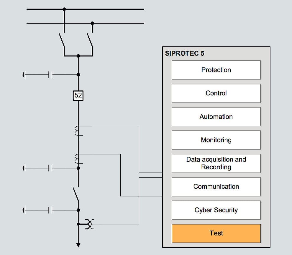
To shorten testing and commissioning times of SIPROTEC relays, extensive test and diagnostic functions are available to the user in DIGSI 5

To shorten testing and commissioning times of SIPROTEC relays, extensive test and diagnostic functions are available to the user in DIGSI 5

Unit protection schemes involve relays that need to communicate with each other. This leads to additional testing requirements. The communications path between the relays is tested using suitable equipment to ensure that the path is complete and that the received signal strength is within specification. Numerical relays may be fitted with loopback test facilities that enable either part of or the entire communications link to be tested from one end.

After completion of these tests, it is usual to enter the relay settings required. This can be done manually via the relay front panel controls, or using a portable PC and suitable software.

Whichever, method is used, a check by a second person that the correct settings have been used is desirable, and the settings recorded. Programmable scheme logic that is required is also entered at this stage.

SIPROTEC relay wiring test editor for monitoring and testing of binary inputs, binary outputs and LED

SIPROTEC relay wiring test editor for monitoring and testing of binary inputs, binary outputs and LED (click to expand)

Current transformer tests

The following tests are normally carried out prior to energisation of the main circuits: checking of polarity and current transformer magnetisation curve.


Polarity check

Each current transformer should be individually tested to verify that the primary and secondary polarity markings are correct (see Figure 1).

The ammeter connected to the secondary of the current transformer should be a robust moving coil, permanent magnet, centre-zero type. A low voltage battery is used, via a single-pole push-button switch, to energise the primary winding. On closing the push-button, the DC ammeter, A, should give a positive flick and on opening, a negative flick.

Current transformer polarity check
Figure 1 – Current transformer polarity check


Checking of magnetisation curve

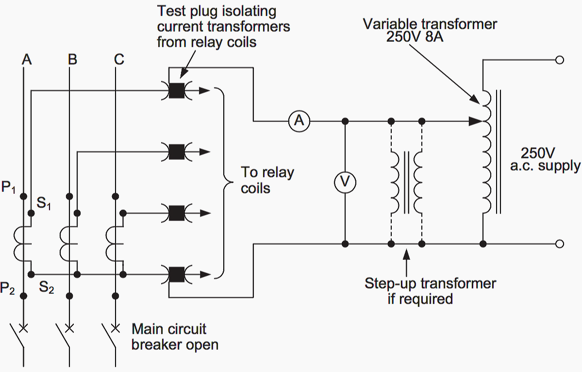
Several points should be checked on each current transformer magnetisation curve. This can be done by energising the secondary winding from the local mains supply through a variable auto-transformer while the primary circuit remains open. See Figure 2.

The characteristic is measured at suitable intervals of applied voltage, until the magnetising current is seen to rise very rapidly for a small increase in voltage. This indicates the approximate knee-point or saturation flux level of the current transformer.

The magnetising current should then be recorded at similar voltage intervals as it is reduced to zero.

Testing current transformer magnetising curve
Figure 2 – Testing current transformer magnetising curve

Care must be taken that the test equipment is suitably rated. The short-time current rating must be in excess of the CT secondary current rating, to allow for measurement of the saturation current. This will be in excess of the CT secondary current rating. As the magnetising current will not be sinusoidal, a moving iron or dynamometer type ammeter should be used.

It is often found that current transformers with secondary ratings of 1A or less have a knee-point voltage higher than the local mains supply. In these cases, a step-up interposing transformer must be used to obtain the necessary voltage to check the magnetisation curve.

Voltage transformer tests

Voltage transformers require testing for polarity, ratio and phasing.


Polarity check of voltage transformer

The voltage transformer polarity can be checked using the method for CT polarity tests. Care must be taken to connect the battery supply to the primary winding, with the polarity ammeter connected to the secondary winding. If the voltage transformer is of the capacitor type, then the polarity of the transformer at the bottom of the capacitor stack should be checked.

Ratio check of VT

This check can be carried out when the main circuit is first made live. The voltage transformer secondary voltage is compared with the secondary voltage shown on the nameplate.

Namplate of a single phase voltage transformer
Namplate of a single phase voltage transformer (photo credit: emadrlc.blogspot.com)


Phasing check of VT

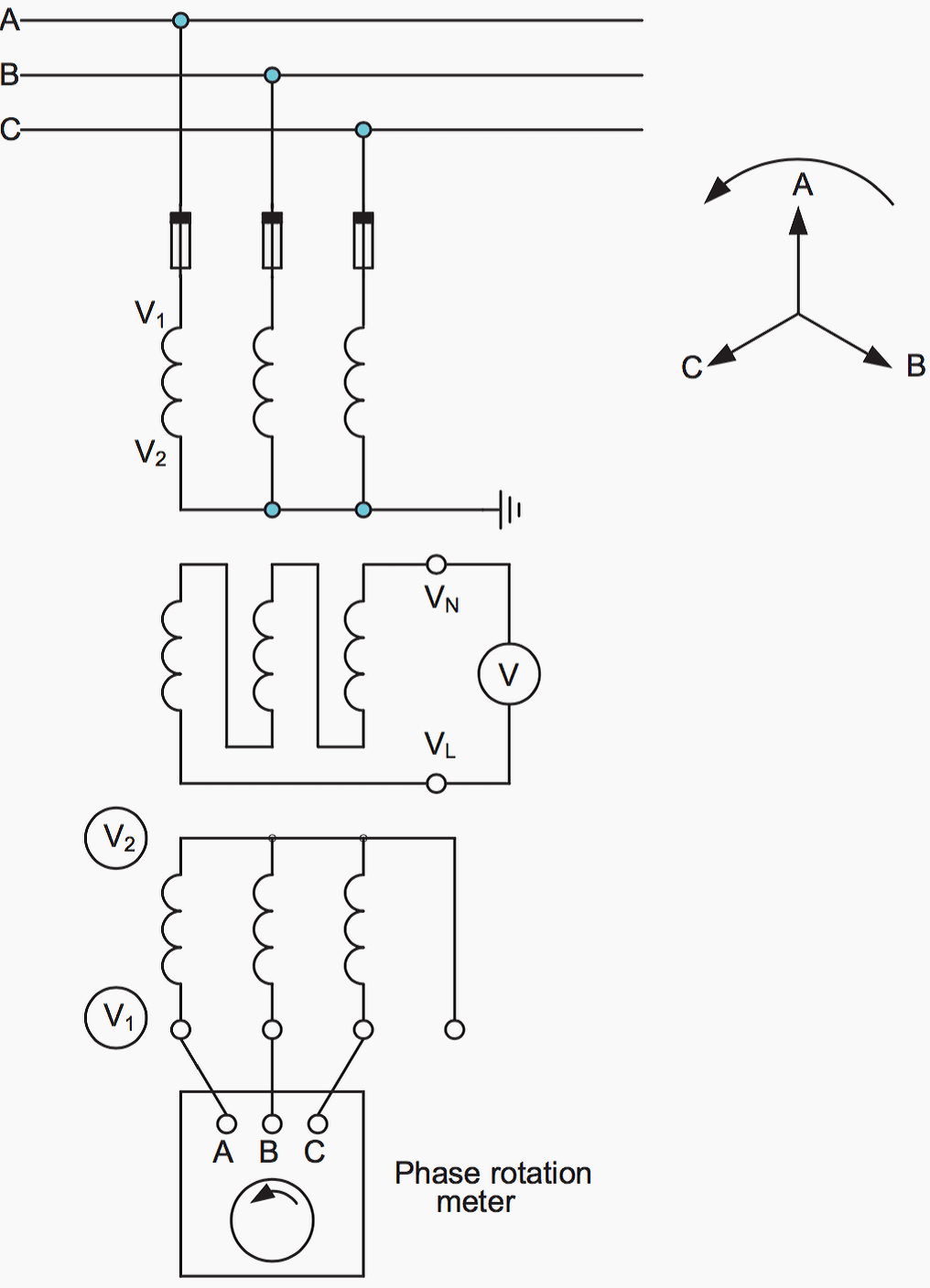
The secondary connections for a three-phase voltage transformer or a bank of three single-phase voltage transformers must be carefully checked for phasing. With the main circuit alive, the phase rotation is checked using a phase rotation meter connected across the three phases, as shown in Figure 3 below.

Provided an existing proven VT is available on the same primary system, and that secondary earthing is employed, all that is now necessary to prove correct phasing is a voltage check between, say, both ‘A’ phase secondary outputs. There should be nominally little or no voltage if the phasing is correct.

However, this test does not detect if the phase sequence is correct, but the phases are displaced by 120o from their correct position, i.e. phase A occupies the position of phase C or phase B in Figure 3.

This can be checked by removing the fuses from phases B and C (say) and measuring the phase-earth voltages on the secondary of the VT. If the phasing is correct, only phase A should be healthy, phases B and C should have only a small residual voltage.

Voltage transformer phasing check
Figure 3 – Voltage transformer phasing check

Correct phasing should be further substantiated when carrying out ‘on load’ tests on any phase-angle sensitive relays, at the relay terminals. Load current in a known phase CT secondary should be compared with the associated phase to neutral VT secondary voltage.

The phase angle between them should be measured, and should relate to the power factor of the system load.

If the three-phase voltage transformer has a broken-delta tertiary winding, then a check should be made of the voltage across the two connections from the broken delta VN and VL, as shown in Figure 3 above. With the rated balanced three- phase supply voltage applied to the voltage transformer primary windings, the broken-delta voltage should be below 5V with the rated burden connected.

Protection relay setting checks (alarm and trip settings)

At some point during commissioning, the alarm and trip settings of the relay elements involved will require to be entered and/or checked. Where the complete scheme is engineered and supplied by a single contractor, the settings may already have been entered prior to despatch from the factory, and hence this need not be repeated.

The method of entering settings varies according to the relay technology used. For electromechanical and static relays, manual entry of the settings for each relay element is required. This method can also be used for digital/numerical relays.

However, the amount of data to be entered is much greater, and therefore it is usual to use appropriate software, normally supplied by the manufacturer, for this purpose. The software also makes the essential task of making a record of the data entered much easier.

Once the data has been entered, it should be checked for compliance with the recommended settings as calculated from the protection setting study. Where appropriate software is used for data entry, the checks can be considered complete if the data is checked prior to download of the settings to the relay.

Otherwise, a check may required subsequent to data entry by inspection and recording of the relay settings, or it may be considered adequate to do this at the time of data entry. The recorded settings form an essential part of the commissioning documentation provided to the client.

Resource // Network protection and automation guide – Areva 

AC 12V-0-12V transformer