Tuesday, 29 July 2025

Why is AC better for long distance power transmission than DC?

Transmission due to the ease of voltage transformation using transformers, which allows for efficient reduction of current and minimizes power losses. While DC power transmission has its advantages, particularly for very long distances and subsea cables, AC's compatibility with existing infrastructure and widespread use makes it the standard for most power grids. 

Here's a more detailed explanation: 

Advantages of AC for Long-Distance Transmission: 
Efficient Voltage Transformation:
AC voltage can be easily stepped up or down using transformers. This is crucial for long-distance transmission because high voltage reduces current, which in turn minimizes power losses due to resistance in the transmission lines.

Reduced Power Loss:
By using high voltage AC, the current is reduced, leading to lower I²R losses (heat losses) in the transmission lines. This makes AC more efficient for delivering power over long distances.
Established Infrastructure:
AC power grids are widely established and have been deployed for decades. This means the infrastructure (transformers, transmission lines, etc.) is readily available and relatively cost-effective to maintain compared to building new DC infrastructure.

Compatibility with End-Use Devices:
Most electrical devices and appliances are designed to operate with AC power, making it a convenient choice for power distribution. 
Why not DC for Long Distance?
While DC has its advantages in certain situations (like HVDC for very long distances and subsea cables), it faces challenges:

Voltage Transformation Complexity:
Converting DC voltage is more complex and expensive than AC voltage conversion. While solid-state converters are now available, they add to the cost and complexity of DC transmission. 
Higher Initial Investment:
Building and maintaining DC transmission lines can be more expensive than AC lines, especially when considering the cost of conversion equipment at both ends. 
Limited Infrastructure:
DC infrastructure is not as widely established as AC, which can make it less practical for general power distribution. 

In summary: AC is the preferred choice for long-distance transmission due to its ease of voltage transformation, reduced power loss at high voltages, and the availability of existing infrastructure. While DC is used in specific applications, particularly for very long distances, AC remains the dominant standard for most power grids.

Short circuit protection circuit


A simple short-circuit protection circuit designed for 12V DC systems, integrating visual and audio indicators for fault detection.
The circuit utilizes a relay as the main switching element, activated by a push-button reset switch. A green "ON LED" indicates normal operation when current flows properly to the output, while a red "SHORT LED" and a buzzer alert the user in case of a short circuit.
The detection mechanism relies on voltage drop across a sensing resistor (1Ω–1.3Ω), which, when excessive, triggers the short circuit path to disable the output and activate the alarm.
This protection system is ideal for low-power DC electronics, safeguarding connected devices from damage due to unintended shorts.

Monday, 28 July 2025

The Heart of a Matter


The Heart of the Matter: A DIY ECG/EKG Circuit Explained

Ever wondered about the electronics behind a heartbeat monitor? This fantastic diagram illustrates the fundamental principles of a single-lead

Electrocardiogram (ECG or EKG) circuit, showing how a biological signal is captured, processed, and displayed.

Let's break down the key stages:

1. Signal Acquisition: Electrodes placed on the body pick up the heart's very faint electrical pulses.

2. Amplification: The heart of the circuit is the AD624 Instrumentation Amplifier. Its job is to take that tiny, microvolt-level signal and boost it significantly while rejecting common noise from the body.

3. Filtering: A simple Low-Pass Filter is used after the amplifier to clean up the signal, removing high-frequency noise (like muscle tremors or 60Hz power line interference) to reveal the classic, clear ECG waveform.

4. Display: The final analog signal is then converted and sent to a computer to be visualized.

CRITICAL SAFETY DISCLAIMER: This diagram is for educational and informational purposes ONLY and is NOT a medical device. Building and connecting homemade electronic circuits to the human body is inherently dangerous. This should only be attempted by experienced individuals with a deep understanding of biomedical electronics, signal isolation, and electrical safety. Never use a DIY device for medical diagnosis or treatment.

Sunday, 27 July 2025

Do solar panels generate DC or AC?


Solar panels generate direct current (DC) electricity.
This DC electricity is then converted to alternating current (AC) by an inverter before it can be used to power most household appliances or be sent to the electrical grid. 

Here's a more detailed explanation: 
DC Electricity:
Solar panels, also known as photovoltaic (PV) panels, work by converting sunlight into DC electricity. In DC, the electrical current flows in one direction.

AC Electricity:
Most homes and the electrical grid use alternating current (AC). In AC, the electrical current periodically reverses direction.

Inverters:
An inverter is a device that takes the DC electricity produced by solar panels and converts it into AC electricity.
This conversion is necessary because most household appliances and the electrical grid are designed to use AC power.

Saturday, 26 July 2025

Why can't we big capacitors instead of batteries to store energy?


While capacitors can store energy, they are generally not suitable as a direct replacement for batteries due to their lower energy density, shorter discharge times, and inability to maintain a stable voltage during discharge. 

Here's a more detailed explanation:
1. Lower Energy Density:
Batteries store energy through electrochemical reactions, allowing them to pack a large amount of energy into a relatively small volume and weight. 
Capacitors store energy electrostatically by accumulating charge on their plates. This method results in significantly lower energy density compared to batteries. 
For the same amount of stored energy, a capacitor would be much larger and heavier than a battery. 

2. Shorter Discharge Times:
Capacitors discharge energy very quickly, while batteries can provide a sustained and stable power output over a longer period. 
A capacitor's voltage drops linearly as it discharges, making it unsuitable for applications requiring a constant voltage supply. 
Batteries, on the other hand, maintain a more stable voltage output until they are nearly depleted. 

3. Inability to Maintain Constant Voltage:
As a capacitor discharges, its voltage decreases, which can be problematic for many electronic devices that require a stable voltage input. 
Batteries offer a relatively constant voltage throughout their discharge cycle, making them a better choice for powering devices that need a consistent voltage supply. 

4. Applications:
While not ideal for long-term energy storage, capacitors are well-suited for applications requiring bursts of high power or quick charging and discharging, such as regenerative braking systems in vehicles. 
Batteries are more appropriate for applications requiring sustained power delivery over extended periods, like powering portable electronics, electric vehicles, and energy storage systems. 

In summary: While capacitors and batteries both store energy, their fundamental differences in energy density, discharge characteristics, and voltage stability make batteries the preferred choice for most long-term energy storage applications.

Friday, 25 July 2025

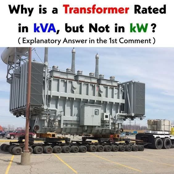
Why is transformer rated in KVA, but not in KW?


Transformers are rated in kVA (kilovolt-amperes) instead of kW (kilowatts) because kVA represents the apparent power, which includes both real and reactive power, while kW only represents the real power.
The power factor, which determines the proportion of real and reactive power, can vary depending on the load connected to the transformer. Since the transformer's losses (copper and core losses) depend on the current and voltage, not the power factor, kVA is a more consistent and accurate way to rate a transformer's capacity, regardless of the connected load. 

Here's a more detailed explanation:
Real Power (kW):
This is the power that is actually converted into work, like heat or mechanical energy, by the load. 

Reactive Power (kVAR):
This is the power that oscillates between the source and the load due to inductive or capacitive loads, and does not contribute to useful work. 

Apparent Power (kVA):
This is the vector sum of real and reactive power. It represents the total power that the transformer needs to handle, regardless of the power factor. 

Power Factor:
The power factor is the ratio of real power to apparent power (kW/kVA). It indicates how efficiently the power is being used. A power factor of 1 means all power is real power, while a power factor less than 1 means some power is reactive. 

Transformer Losses:
Transformer losses (copper and core losses) are primarily dependent on the voltage and current flowing through the transformer, not the power factor. Since kVA is directly related to voltage and current, it provides a more reliable measure of the transformer's capability to handle these losses. 

Load Variability:
When a transformer is designed, the manufacturer doesn't know what kind of load (resistive, inductive, or capacitive) will be connected to it in the future. Therefore, kVA is used as a universal rating that applies to all types of loads. 

In summary, kVA is used as the standard rating for transformers because it provides a more accurate and consistent measure of the transformer's capacity to handle power, regardless of the load's power factor.

Thursday, 24 July 2025

If one phase power is 220V, why is three phase 220V, not 660V.


In a three-phase system, the voltage between two phases is not simply the sum of the individual phase voltages (220V + 220V = 440V) because the phases are shifted by 120 degrees from each other.
This means the voltages don't reach their peak values at the same time. When calculating the voltage between two phases, you must use vector addition (or phasor addition), which takes into account the phase difference. The resulting line-to-line voltage in a 3-phase system is approximately 1.732 (the square root of 3) times the phase voltage, which is why a 220V phase voltage results in a 380-400V line voltage, not 660V. 

Elaboration:
1. Phase Shift:
In a three-phase system, each phase voltage is 120 degrees out of phase with the others. This means they don't reach their peak positive or negative values simultaneously. 

2. Vector Addition:
When calculating the voltage between two phases (line-to-line voltage), you are essentially finding the resultant voltage of two vectors (phasors) that are 120 degrees apart. 

3. Square Root of 3:
The line-to-line voltage in a balanced three-phase system is calculated by multiplying the phase voltage by the square root of 3 (approximately 1.732). For example, if the phase voltage is 220V, the line voltage would be approximately 220 * 1.732 = 381V, which is typically rounded to 400V.

4. Why not 660V?
If you were to simply add the phase voltages arithmetically (220V + 220V + 220V = 660V), you would be ignoring the phase shift and assuming they all reach their peak values at the same time, which is not the case in a three-phase system.

5. Practical Considerations:
While the theoretical line-to-line voltage is 400V, the actual measured voltage can vary slightly due to factors like system loading and voltage drops, according to an electrical forum.