Tuesday, 15 April 2025

Shedding Light on Automatic Road Light Control

Shedding Light on Automatic Road Light Control

This circuit diagram illustrates a simple yet effective automatic road light on/off system using:
1. an IRFZ44N MOSFET,
2. an LDR (Light Dependent Resistor),
3. and a 12V DC power supply.

The core idea is to automate the road light's operation based on ambient light levels, turning it on at dusk and off at dawn.
The IRFZ44N, a power MOSFET, acts as a switch to control the road light. It is driven by the LDR, which senses light intensity.
When light levels drop (e.g., at night), the LDR's resistance increases, allowing the MOSFET to turn on the road light. Conversely, during the day, the LDR's resistance decreases, turning off the MOSFET and the light. The circuit is powered by a 12V DC input, suitable for many road lighting applications.

Components and connections: 
The IRFZ44N MOSFET has three pins: Gate, Drain, and Source. The Drain is connected to the negative terminal of the road light, while the positive terminal of the light is connected to the 12V DC supply. The Source pin of the MOSFET is grounded. The Gate pin, which controls the MOSFET's switching, is connected to a voltage divider formed by the LDR and a 100kΩ resistor. The LDR is connected between the Gate and ground, while the 100kΩ resistor is connected between the Gate and the 12V supply.
This setup ensures that the Gate voltage changes with the LDR's resistance, which varies with light intensity. When the LDR resistance is high (in darkness), the Gate voltage rises, turning on the MOSFET and the road light. When the LDR resistance is low (in daylight), the Gate voltage drops, turning off the MOSFET.

This design is both energy-efficient and practical for street lighting applications.
The LDR ensures the light only operates when needed, reducing power consumption. The IRFZ44N MOSFET is a robust choice, capable of handling the current required for a road light while offering low on-resistance for minimal power loss. 
However, the circuit's simplicity means it lacks features like adjustable sensitivity or protection against voltage spikes, which might be necessary for real-world deployment. Adding a potentiometer in series with the LDR could allow fine-tuning of the light threshold, and a diode across the road light could protect the MOSFET from inductive spikes.
Overall, this circuit demonstrates a fundamental approach to automating lighting systems using basic electronic components.

Monday, 14 April 2025

AC vs DC: A Water Flow Analogy for Understanding Electrical Currents

The image shows a simple analogy to explain the difference between Direct Current (DC) and Alternating Current (AC) using the flow of water in a hose as a metaphor for electrical current. In the top section labeled "DC," the illustration shows water flowing in one consistent direction through a hose, represented by a straight arrow.
The graph where the current (y-axis) remains constant over time (x-axis), indicating that DC flows steadily in a single direction.
Examples are devices like a computer, smartphone, and television, "Things that use DC," highlighting that DC is typically used in electronics requiring a stable, unidirectional flow of electricity, such as batteries and low-voltage devices.

In the bottom section "AC," the image depicts water oscillating back and forth in the hose, with arrows pointing in both directions to show the alternating flow.
The graph displays a sinusoidal wave, where the current fluctuates between positive and negative values over time, illustrating AC's characteristic of periodically reversing direction.
Examples are power line and a wall outlet, labeled "Things that use AC," indicating that AC is commonly used for power distribution in homes and industries due to its ability to be easily transformed and transmitted over long distances with minimal energy loss. 

Sunday, 13 April 2025

Fuse wires are always thin why?

Fuse wires are designed to be thin for several important reasons related to their function in electrical circuits.
1. Purpose of a Fuse Wire
A fuse is a safety device that protects electrical circuits from excessive current. When the current exceeds a safe limit, the fuse wire melts and breaks the circuit, preventing damage to appliances, wiring, or fire hazards.

2. Why Thin Wires Are Used

a) Low Melting Point Requirement
- Thin wires have less cross-sectional area, meaning they have higher resistance per unit length compared to thicker wires.  
- According to Joule’s Law of Heating (\(H = I^2 R t\)), a thin wire heats up faster for a given current due to higher resistance.  
- Since thin wires have less material to absorb heat, they melt quickly when current exceeds the rated limit.  

b) Faster Response to Overcurrent
- Thinner wires have less thermal mass, meaning they heat up and melt faster in case of a fault (short circuit or overload).  
- This quick response prevents damage to sensitive electronic components.  

c) Material Selection & Current Rating
- Fuse wires are made from low-melting-point materials like tin, lead, or alloys (e.g., tin-lead, copper, or silver with controlled resistance).  
- The thickness is chosen based on the current rating (e.g., a 5A fuse will have a thinner wire than a 15A fuse).  

d) Cost-Effectiveness & Reliability
- Thin wires are cheaper and easier to manufacture while still providing precise protection.  
- A thicker wire would require much higher current to melt, defeating the purpose of a fuse.  

3. Key Factors in Fuse Wire Design
- Material: Low melting point (e.g., tin melts at 232°C, lead at 327°C).  
- Diameter: Precisely calibrated to melt at a specific current.  
- Heat Dissipation: Thin wires do not dissipate heat efficiently, ensuring quick melting.  

Conclusion
Fuse wires are thin to ensure they melt quickly and reliably when excess current flows, providing effective circuit protection. If they were thick, they would not respond fast enough, leading to potential hazards.  

Thursday, 10 April 2025

How to Size a Grounding Electrode Conductor (GEC)?

How to Size a Grounding Electrode Conductor (GEC)?
Let’s break it down in detail based on the National Electrical Code (NEC), particularly NEC Article 250, which governs grounding and bonding.

What is a Grounding Electrode Conductor (GEC)?

A Grounding Electrode Conductor (GEC) is the wire that connects the grounding system of an electrical installation (typically the main service panel or equipment) to the grounding electrode, such as a ground rod, ground plate, or building steel. The purpose is to safely dissipate fault currents and lightning surges into the earth.

Why Is Sizing Important?

The GEC must be properly sized to:

- Withstand available fault current
- Ensure safety and compliance
- Protect electrical systems and equipment

How to Size a GEC?

1. Determine the Size of the Largest Ungrounded Service-Entrance Conductor or Equivalent

This means you first look at the size of the service conductors (hot wires) entering the building.

2. Refer to NEC Table 250.66

This table is used to determine the minimum size of the GEC, based on the size of the largest ungrounded service-entrance conductor or equivalent area for parallel conductors.

Here’s a simplified version:
Note: Aluminum GECs must be one size larger than copper.

Special Considerations:

If Connecting to a Ground Rod Only (Rod, Pipe, or Plate Electrodes):

NEC 250.66(A) allows the conductor to be no smaller than 6 AWG copper or 4 AWG aluminum, regardless of service size. That's because the resistance of the ground rod limits current flow, making larger wires unnecessary.

Multiple Grounding Electrodes:

If multiple grounding electrodes are used (like rods and rebar), you still only need to size the GEC based on the largest conductor entering the building—not the total combined grounding electrode area.

Conductors in Parallel:

If you have conductors in parallel, you add the cross-sectional areas to determine equivalent size, and then refer to Table 250.66.

Example:

Let’s say your service-entrance conductors are 3/0 AWG copper.

According to NEC Table 250.66, the GEC must be at least 4 AWG copper.

But if you're just connecting to a ground rod, you can use 6 AWG copper, even if your service is large.

Visual Breakdown (based on the image):

Grounding Rod: The metal rod driven into the earth to make an electrical connection with the ground.

Grounding Electrode Conductor (GEC): The wire connecting your electrical system to the grounding rod.

Proper clamping and secure connection are essential for continuity and safety.


Wednesday, 2 April 2025

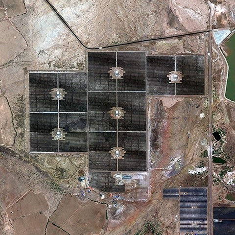
The Gujarat Hybrid Renewable Energy Park

The Gujarat Hybrid Renewable Energy Park is one of the world’s largest renewable energy projects, combining solar and wind energy on a massive scale. Here are the key details:
Overview
- Location: Kutch district, Gujarat, India  
- Total Planned Capacity: 30 GW (gigawatts)  
- Land Area: 72,600 hectares (approx. 726 sq km)  
- Developed by: Gujarat Hybrid Renewable Energy Park Ltd (GHPCL) – a joint venture between Gujarat government (Gujarat Power Corporation Ltd - GPCL) and private renewable energy companies
- Estimated Investment: Over ₹1.5 lakh crore (~$20 billion)  

Hybrid Energy Components
1. Solar Power – Large-scale photovoltaic (PV) plants  
2. Wind Power – Onshore and potentially offshore wind farms  
3. Energy Storage – Battery storage & pumped hydro to ensure stable supply  

Key Features
- World’s Largest Renewable Energy Park (once fully operational)  
- Supports India’s 500 GW renewable energy target by 2030
- Reduces carbon emissions by ~50 million tons/year
- Hybrid model ensures consistent power generation (solar by day, wind often at night)  

Progress & Timeline
- Phase 1 (2022-2025): 5 GW already under development  
- Full Completion: Expected by 2030
- Major Investors: Adani Green, Suzlon, ReNew Power, and other global players  

Benefits
✔ Boosts Gujarat’s green energy leadership
✔ Creates jobs & economic growth in Kutch
✔ Supports India’s net-zero emissions goal by 2070
✔ Attracts foreign investment in renewables

This project is a cornerstone of India’s transition to clean energy and positions Gujarat as a global renewable energy hub.

Tuesday, 1 April 2025

What happens if you supply 220V DC to the transformer

Supplying 220V DC to a transformer designed for AC input can cause serious problems, including potential damage or failure.
Here’s why:

1. Transformers Work on AC, Not DC
   - Transformers rely on changing magnetic fields (Faraday’s Law of Induction) to transfer energy from the primary to the secondary winding.
   - DC voltage does not change over time, so it cannot create a varying magnetic field.
   - Without a changing magnetic field, no voltage is induced in the secondary winding.

2. Consequences of Applying DC to a Transformer
   - High Current Draw (Almost Like a Short Circuit):
     - The primary winding of a transformer has very low DC resistance (only wire resistance).
     - Applying DC causes a large current to flow (since there’s no inductive reactance to limit it).
   - Overheating & Burnout:
     - The excessive current can overheat the windings, damaging insulation and possibly melting wires.
   - Core Saturation:
     - The transformer core can become magnetically saturated, further increasing current and heat.
   - Possible Smoke/Fire Risk:
     - If the transformer is not protected (e.g., by a fuse), it may burn out, smoke, or even catch fire.

3. Will the Secondary Output Any Voltage?
   - No, because DC does not create a changing magnetic flux.
   - The only voltage you might see is a brief spike when connecting/disconnecting DC, but this is not useful and can be dangerous.

4. Exceptions (Special Cases)
   - Some pulse transformers or flyback converters can handle DC pulses, but standard AC transformers cannot.
   - If you need to step up/down DC, use a DC-DC converter instead.

Conclusion
⚠️ Never apply DC to an AC transformer—it will likely overheat, burn out, or fail catastrophically. Always use the correct input voltage type (AC for traditional transformers).  

If you need to convert DC, consider using:
- Buck/Boost Converters (for DC-DC conversion)
- Inverters (to convert DC to AC first)  

Regulated Power Supply Block Diagram