Tuesday, 24 December 2024

Why do wind turbine produce AC not DC?

The almost universal practice with electricity-producing wind turbines, whether large or small, is to use alternators, which produce alternating current (AC). The design details of these vary greatly.

Nearly all small wind turbines use relatively simple permanent magnet alternators, which employ a rotating rotor with some number of permanent magnets, which induce an electromotive force in the coils of the nonmoving stator. This type of design produces AC quite naturally, but because the wind turbine’s rate of rotation changes with wind speed and electrical load, the sine wave of the current constantly varies in both frequency and amplitude (voltage).

The advantage of this type of design, instead of using a DC generator is that alternators do not require a commutator mechanism, which has brushes usually made out of graphite that require periodic replacement, add friction, and create graphite residue as the brushes wear down.

This type of AC is very different than the tightly controlled AC that is used for commercial power and is called wild power.

To make use of wild power, it is necessary to tame or condition it to make it useful. One way is to convert the raw AC into DC by passing it through a bridge rectifier. From there, further conditioning can be performed using a variety of active and passive circuits and/or a battery bank that absorbs and smooths the DC power.

Finally, this DC power, in useful form, can be used directly or used to make standardized AC power by means of an inverter.

Monday, 23 December 2024

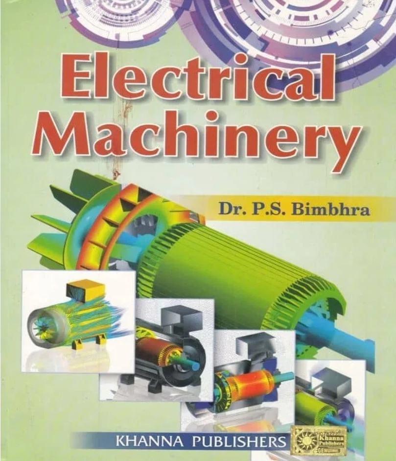
Electrical Machinery Book PDF

                   Download Now: Link

Electrical machinery is essential for modern engineering, powering industries, homes, and innovative technologies. For students, professionals, and hobbyists, having access to free PDFs on machinery can be a game-changer. 

Machinery encompasses devices that convert electrical energy into mechanical energy or vice versa. Examples include motors, generators, transformers, and various auxiliary devices.

Importance:
machinery drives industries, enabling automation and efficient energy transfer.

Examples:
Motors: Convert electrical energy into mechanical work.
Generators: Produce electrical power from mechanical energy.
Transformers: Alter voltage levels in power systems.

Understanding these devices is critical for anyone studying or working in electrical engineering.


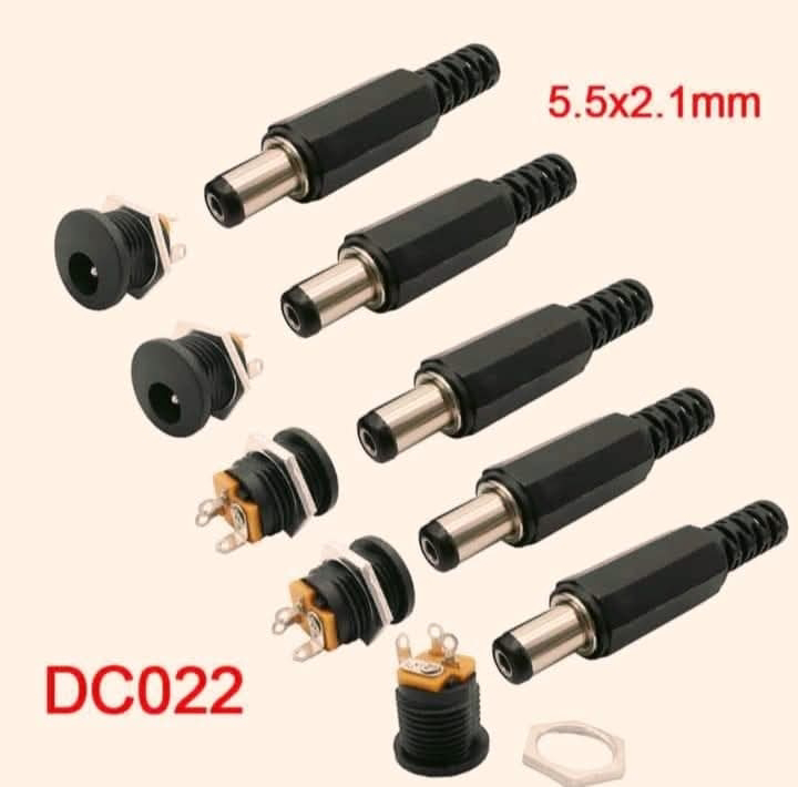
DC power connectors

DC power connectors are used to connect DC power sources to devices.
Here are some common types:
Common DC Power Connectors

1. Barrel Connector: A cylindrical connector with a central pin, often used for DC power adapters.
2. DC Jack: A female connector that accepts a DC plug, commonly used on devices like laptops and routers.
3. DC Plug: A male connector that connects to a DC jack, often used on DC power adapters.
4. USB: While primarily used for data transfer, USB ports can also supply DC power (up to 2.5A).
5. Molex: A type of connector commonly used on PC power supplies and hard drives.
6. JST: A type of connector often used on batteries and other DC-powered devices.

DC Power Connector Specifications
1. Voltage Rating: The maximum voltage the connector can handle.
2. Current Rating: The maximum current the connector can handle.
3. Polarity: The orientation of the positive (+) and negative (-) terminals.
4. Locking Mechanism: Some connectors have a locking mechanism to secure the connection.

Examples of DC Power Connectors
1. 5.5mm x 2.5mm Barrel Connector: Commonly used on DC power adapters.
2. 2.1mm x 5.5mm DC Jack: Often used on devices like routers and modems.
3. USB-C (USB Type-C): A reversible, faster, and more powerful USB connector that can supply up to 100W of power.

When selecting a DC power connector, ensure it matches the device's requirements and specifications.

Sunday, 22 December 2024

Motor start stop and control circuit

What's this circuit for? 
This circuit diagram represents a control circuit typically used for a motor control system with two push buttons (SB1 and SB2) and a contactor setup (KM and KA).
Here’s a breakdown of its function:

1. Start and Stop Control:
   - SB1 (Start Button): When pressed, it energizes the circuit, allowing current to flow and starting the motor.
   - SB2 (Stop Button): When pressed, it interrupts the circuit, stopping the motor.

2. Contactor Operation:
   - KM: This is the main contactor that controls the motor. When energized, it closes its contacts to allow power to the motor.
   - KA: This is likely an auxiliary contactor, which may be used for additional control or safety functions.

3. Relay (KT): This is a relay that helps with the control logic, ensuring that the motor can be started and stopped properly.

Summary
In summary, this circuit is used to control the starting and stopping of a motor using two push buttons.
It safely manages the operation of the motor, allowing for easy control and automation in various applications, such as industrial machinery or HVAC systems.