Thursday 6 July 2023

Address power outage

What are the common issues that can arise in electrical power distribution systems, and how can they be addressed?
Here are some of the common issues that can arise in electrical power distribution systems:

1. Overload: This occurs when the demand for electricity exceeds the capacity of the system. This can be caused by a sudden increase in demand, such as a heat wave or a power plant outage, or by a gradual increase in demand, such as the growth of a city. Overloads can cause voltage drops and outages.

2. Undervoltage: This occurs when the voltage of the electricity is lower than the standard voltage. This can be caused by a number of factors, including overloading, line losses, and bad weather. Undervoltage can cause equipment to malfunction and can be a safety hazard.

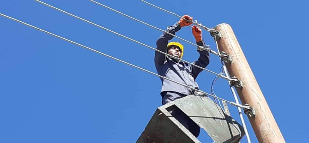
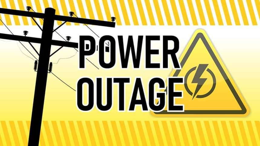
3. Outages: This occurs when the electricity is not available to customers. Outages can be caused by a number of factors, including equipment failures, natural disasters, and human error. Outages can be disruptive and can cause economic losses.

4. Power quality: This refers to the quality of the electricity. Power quality problems can be caused by a number of factors, including voltage fluctuations, harmonics, and noise. Power quality problems can cause equipment to malfunction and can be a safety hazard.

5. Cybersecurity: This refers to the security of the electrical power distribution system from cyberattacks. Cyberattacks can cause outages, damage equipment, and disrupt the flow of electricity.

There are a number of ways to address these issues. Some of the most common methods include:

1. Overload protection: This can be provided by using fuses, circuit breakers, and other devices that will disconnect the circuit if the current exceeds the safe value.

2. Undervoltage protection: This can be provided by using surge suppressors and other devices that will raise the voltage to the standard level.

3. Outage protection: This can be provided by using backup generators and other devices that will provide electricity to customers in the event of an outage.

4. Power quality improvement: This can be provided by using filters and other devices that will reduce voltage fluctuations, harmonics, and noise.

5. Cybersecurity: This can be provided by using firewalls, intrusion detection systems, and other security measures to protect the system from cyberattacks.

By addressing these issues, it is possible to improve the reliability, safety, and efficiency of electrical power distribution systems.
 
Video: https://youtu.be/YWw5W8esJNE

Wednesday 5 July 2023

Double line to ground fault

A double line-to-ground fault (DLG) is a type of electrical fault that occurs when two conductors of a three-phase system are shorted to ground. This type of fault can cause a significant amount of current to flow, which can damage equipment and disrupt service.
The most common cause of a DLG fault is a loose or damaged electrical connection. Other causes can include:

Defective equipment
Lightning strikes
Grounding problems
DLG faults can be dangerous, and it is important to take steps to prevent them. Some of the things that can be done to prevent DLG faults include:

Regularly inspecting and testing electrical equipment
Using the proper grounding methods
Installing surge protection devices
Educating employees about the dangers of DLG faults

If a DLG fault does occur, it is important to take steps to de-energize the circuit as quickly as possible. This can be done by opening the circuit breaker or fuse that protects the circuit. Once the circuit is de-energized, a qualified electrician should be called to inspect the damage and make repairs.

Here are some of the effects of a DLG fault:

High current flow can damage equipment and cause fires.
Fault current can flow through other equipment, which can disrupt service.
Fault current can cause voltage drop, which can affect the operation of equipment.
It is important to take steps to prevent DLG faults and to be aware of the potential effects of these faults.

Here are some additional details about DLG faults:

The current that flows through a DLG fault is typically much higher than the current that flows through a normal load. This is because the fault path offers much lower resistance than the normal load path.

The high current that flows through a DLG fault can cause a number of problems, including:
Equipment damage
Fires
Disruption of service
Voltage drop

It is important to take steps to prevent DLG faults and to be aware of the potential effects of these faults.
 

Tuesday 4 July 2023

Installation of mechanical structure of PV (photovoltaic) modules

The process of installing the mechanical structure and mounting of PV (photovoltaic) modules:
The installation of a PV system involves several steps, including the design, electrical and mechanical installation, and commissioning of the system. The mechanical installation process involves installing the mounting structure and mounting the PV modules.

1. Designing the Mounting Structure:
Before installing the mounting structure, an engineer needs to design the structure based on the size and weight of the PV modules and the location of the system. The mounting structure is usually made of aluminum or steel and can be installed on the roof or ground.

2. Preparing the Site:
The installation site should be prepared before mounting the PV modules. The area should be cleared of any obstacles that could block sunlight, and any debris or dirt should be removed from the area. The mounting location should be level and free of any obstructions.

3. Installing the Mounting Structure:
The mounting structure is usually assembled on the ground and then lifted onto the roof or ground. The mounting structure is secured to the roof or ground using bolts or screws. The mounting structure should be properly grounded to ensure the safety of the PV system.

4. Mounting the PV Modules:
Once the mounting structure is installed, the PV modules can be mounted on the structure. The PV modules are usually mounted using clamps that hold the modules in place. The clamps are secured to the mounting structure using bolts or screws.

5. Wiring the PV Modules:
After mounting the PV modules, the wiring of the system can begin. The PV modules are connected in series or parallel to create a string. The strings are then connected to the inverter, which converts the DC power generated by the PV modules into AC power that can be used by the electrical grid.

6. Commissioning the System:
Once the PV system is installed, it should be commissioned to ensure that it is working correctly. The commissioning process involves testing the system's electrical components, including the inverter and PV modules, and verifying that the system is generating the expected amount of power.

7. Ongoing Maintenance:
Once the PV system is commissioned and operational, it is important to maintain the system regularly to ensure its long-term performance. Routine maintenance activities may include cleaning the PV modules to remove any debris or dirt that could reduce their efficiency, checking the wiring connections for any signs of wear or damage, and inspecting the mounting structure to ensure it is still securely anchored to the roof or ground.

8. Safety Considerations:
During the installation process, safety should always be a top priority. It is important to follow all safety guidelines and use the appropriate personal protective equipment (PPE) to prevent injury. For example, when installing the mounting structure, workers should use fall protection equipment to prevent falls from the roof or elevated structure. Similarly, when working on the electrical components of the system, workers should ensure that the system is de-energized and follow appropriate lockout/tagout procedures.

In summary, the installation of a PV system requires careful planning, design, and execution to ensure a safe and efficient installation. Installing the mechanical structure and mounting PV modules is a critical step in the installation process that requires a strong understanding of the engineering and construction principles involved. By following the appropriate guidelines and safety procedures, a successful installation can be achieved that will generate clean, renewable energy for years to come.
 

Monday 3 July 2023

Three phase to ground fault

A three-phase to-ground fault is a type of electrical fault that occurs when one or more of the three phases of an electrical system is shorted to ground. This type of fault can cause a significant amount of current to flow, which can damage equipment and disrupt service.
There are a number of different causes of three-phase to-ground faults, including:

1. Loose or damaged electrical connections

2. Defective equipment

3. Lightning strikes

4. Grounding problems

Three-phase to-ground faults can be dangerous, and it is important to take steps to prevent them. Some of the things that can be done to prevent three-phase to-ground faults include:

1. Regularly inspecting and testing electrical equipment

2. Using the proper grounding methods

3. Installing surge protection devices

4. Educating employees about the dangers of three-phase to-ground faults

If a three-phase to-ground fault does occur, it is important to take steps to de-energize the circuit as quickly as possible. This can be done by opening the circuit breaker or fuse that protects the circuit. Once the circuit is de-energized, a qualified electrician should be called to inspect the damage and make repairs.

Here are some of the effects of three-phase to ground faults:

1. High current flow can damage equipment and cause fires.

2. Fault current can flow through the ground, which can cause grounding problems.

3. Fault current can flow through other equipment, which can disrupt service.

4. Fault current can cause voltage drop, which can affect the operation of equipment.

It is important to take steps to prevent three-phase to-ground faults and to be aware of the potential effects of these faults.
 

Transmission and distribution substation

An electrical substation is an installation used for the transformation, switching, protection and control of electrical energy. They are used to receive electricity from a power station and then distribute it to homes and businesses. Substations are located throughout the country, and they are essential for the reliable delivery of electricity.
Substations are typically large and complex facilities, and they can be divided into two main types: transmission substations and distribution substations.
Transmission substations are located near power stations, and they are responsible for increasing the voltage of electricity so that it can be transmitted over long distances. Distribution substations are located closer to homes and businesses, and they are responsible for decreasing the voltage of electricity so that it can be used safely.
Substations contain a variety of equipment, including transformers, circuit breakers, switches, and insulators. Transformers are used to increase or decrease the voltage of electricity. Circuit breakers are used to protect the equipment in the substation from damage in the event of a short circuit. Switches are used to connect and disconnect the equipment in the substation. Insulators are used to prevent electricity from flowing to ground.
Substations are essential for the reliable delivery of electricity. They help to ensure that homes and businesses have access to a safe and reliable supply of electricity.
 

Tuesday 27 June 2023

Common problems of an inverter

The inverter is a critical component of a solar power system that converts the DC power generated by the solar panels into AC power that can be used to power household loads or fed back into the grid. If the inverter is not functioning properly, it can significantly impact the performance and efficiency of the entire solar power system. Here are some signs that your inverter may need to be replaced:
1. Low or No Power Output: If your solar power system is not generating as much power as it should, or if there is no power output at all, it could be a sign that the inverter is not functioning properly.

2. Error Messages or Warning Lights: Some inverters have built-in error messages or warning lights that indicate when there is a problem. If you see an error message or warning light, it could be a sign that the inverter needs to be replaced.

3. Overheating: If the inverter is getting too hot, it may shut down automatically or reduce its power output. Overheating can be caused by a variety of factors, including poor ventilation or a malfunctioning cooling system.

4. Unusual Noises: If you hear unusual noises coming from the inverter, such as buzzing or humming, it could be a sign of a problem. This could be caused by a faulty fan or other internal component.

5. Age: Inverters typically have a lifespan of 10 to 15 years. If your inverter is approaching or exceeding this age, it may be time to consider replacing it.
If you notice any of these signs, it is important to consult with experienced solar power professionals to diagnose the problem and determine whether the inverter needs to be replaced. In some cases, it may be possible to repair the inverter rather than replacing it, but in other cases, replacement may be the best option to ensure the continued performance and efficiency of your solar power system.

Safety considerations in a MV network work

Safety is a critical consideration for any medium voltage (MV) network, as high voltages can pose a serious risk of electrical shock and other hazards. Some key safety considerations for an MV network include:
1. Personal Protective Equipment (PPE): Workers who are involved in the installation, maintenance, or repair of an MV network should be provided with appropriate personal protective equipment, such as insulated gloves, safety glasses, and flame-resistant clothing.

2. Lockout/Tagout Procedures: Lockout/tagout procedures should be implemented to prevent unexpected energization of equipment while workers are performing maintenance or repair work.

3. Grounding and Bonding: All equipment in the MV network should be properly grounded and bonded to prevent electrical shock and other hazards.

4. Warning Signs and Labels: Warning signs and labels should be placed on equipment and in areas where high voltages are present to warn workers and others of the potential hazards.

5. Electrical Clearances: Minimum electrical clearances should be maintained between equipment and other objects to prevent arcing and other hazards.

6. Safety Interlocks: Safety interlocks, such as door switches and pressure switches, should be installed on equipment to prevent operating equipment while doors are open or pressure is not within the safe range.

7. Proper Equipment Selection: All equipment used in the MV network should be designed and tested to meet appropriate safety standards and should be installed and used in accordance with manufacturer instructions.

8. Training and Education: Workers who are involved in the installation, maintenance, or repair of an MV network should be provided with appropriate training and education on safe work practices and procedures.
It is important to consult with experienced electrical engineers and other professionals to ensure that all necessary safety considerations are taken into account when designing, installing, and maintaining an MV network.

AC 12V-0-12V transformer