Welcome to SparkED, your ultimate destination for all things engineering, science, and innovation! Our blog is a vibrant platform dedicated to showcasing the latest advancements, groundbreaking research, and fascinating discoveries in the world of electrical engineering and beyond.
At SparkED, we believe in the power of knowledge and its ability to ignite extraordinary ideas. Our team of passionate writers and researchers is committed to bringing you captivating articles.
What happens if a phase and neutral of a single-phase energy meter is reversed?
Nothing will happen. the single phase current means alternating current which changes its polarity 50 times per second (frequency), not like direct current DC having fixed polarities of positive and negative all the time . if the polarity of a single phase motor is changed , the motor remain runs in its same direction , but DC motor will reverse its running direction when its polarity changed. same thing will happen in ac energy meter.
Swapping phase and neutral would have no effect whatever, the meter would continue to operate normally.
Exchanging the line and load connections (input and output) would reverse the meter and it would run backwards. Unless it had an anti reverse pawl in which case it wouldn't move.
Nothing,as far as the meter is concerned..it will operate as normal, but unless the error is detected, the wiring to the remainder of the premises would be in a dangerous state.
Installation of protection relays at site creates a number of possibilities for errors in the implementation of the scheme to occur. Even if the scheme has been thoroughly tested in the factory, wiring to the CTs and VTs on site may be incorrectly carried out, or the CTs/VTs may have been incorrectly installed.
The impact of such errors may range from simply being a nuisance (tripping occurs repeatedly on energisation, requiring investigation to locate and correct the errors) through to failure to trip under fault conditions, leading to major equipment damage, disruption to supplies and potential hazards to personnel.
The strategies available to remove these risks are many, but all involve some kind of testing at site. Commissioning tests at site are therefore invariably performed before protection equipment is set to work. The aims of commissioning tests are:
To ensure that the equipment has not been damaged during transit or installation
To ensure that the installation work has been carried out correctly
To prove the correct functioning of the protection scheme as a whole
The tests carried out will normally vary according to the protection scheme involved, the relay technology used, and the policy of the client. In many cases, the tests actually conducted are determined at the time of commissioning by mutual agreement between the client’s representative and the commissioning team.
The following tests are invariably carried out, since the protection scheme will not function correctly if faults exist.
Wiring diagram check, using circuit diagrams showing all the reference numbers of the interconnecting wiring
General inspection of the equipment, checking all connections, wires on relays terminals, labels on terminal boards, etc.
Insulation resistance measurement of all circuits
Perform relay self-test procedure and external communications checks on digital/numerical relays
Check that protection relay alarm/trip settings have been entered correctly
Tripping and alarm circuit checks to prove correct functioning
In addition, the following checks may be carried out, depending on the factors noted above (not covered in this technical article):
Secondary injection test on each relay to prove operation at one or more setting values
Primary injection tests on each relay to prove stability for external faults and to determine the effective current setting for internal faults (essential for some types of electromechanical relays)
Testing of protection scheme logic
Insulation resistance tests
All the deliberate earth connections on the wiring to be tested should first be removed, for example earthing links on current transformers, voltage transformers and DC supplies. Some insulation testers generate impulses with peak voltages exceeding 5kV. In these instances any electronic equipment should be disconnected while the external wiring insulation is checked.
The insulation resistance should be measured to earth and between electrically separate circuits. The readings are recorded and compared with subsequent routine tests to check for any deterioration of the insulation.
The insulation resistance measured depends on the amount of wiring involved, its grade, and the site humidity. Generally, if the test is restricted to one cubicle, a reading of several hundred megohms should be obtained. If long lengths of site wiring are involved, the reading could be only a few megohms.
Protection relay self-test procedure
Digital and numerical relays will have a self-test procedure that is detailed in the appropriate relay manual. These tests should be followed to determine if the relay is operating correctly.
This will normally involve checking of the relay watchdog circuit, exercising all digital inputs and outputs and checking that the relay analogue inputs are within calibration by applying a test current or voltage.
For these tests, the relay outputs are normally disconnected from the remainder of the protection scheme, as it is a test carried out to prove correct relay, rather than scheme, operation.
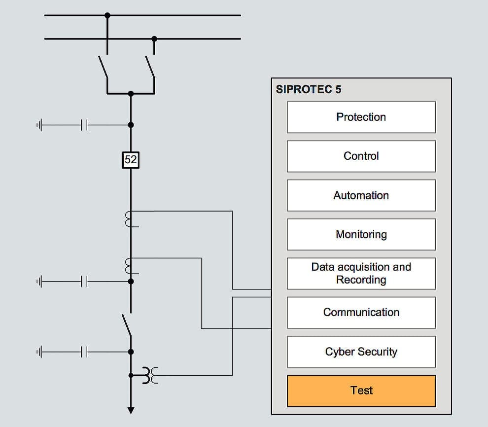
To shorten testing and commissioning times of SIPROTEC relays, extensive test and diagnostic functions are available to the user in DIGSI 5
Unit protection schemes involve relays that need to communicate with each other. This leads to additional testing requirements. The communications path between the relays is tested using suitable equipment to ensure that the path is complete and that the received signal strength is within specification. Numerical relays may be fitted with loopback test facilities that enable either part of or the entire communications link to be tested from one end.
After completion of these tests, it is usual to enter the relay settings required. This can be done manually via the relay front panel controls, or using a portable PC and suitable software.
Whichever, method is used, a check by a second person that the correct settings have been used is desirable, and the settings recorded. Programmable scheme logic that is required is also entered at this stage.
SIPROTEC relay wiring test editor for monitoring and testing of binary inputs, binary outputs and LED (click to expand)
Each current transformer should be individually tested to verify that the primary and secondary polarity markings are correct (see Figure 1).
The ammeter connected to the secondary of the current transformer should be a robust moving coil, permanent magnet, centre-zero type. A low voltage battery is used, via a single-pole push-button switch, to energise the primary winding. On closing the push-button, the DC ammeter, A, should give a positive flick and on opening, a negative flick.
Figure 1 – Current transformer polarity check
Checking of magnetisation curve
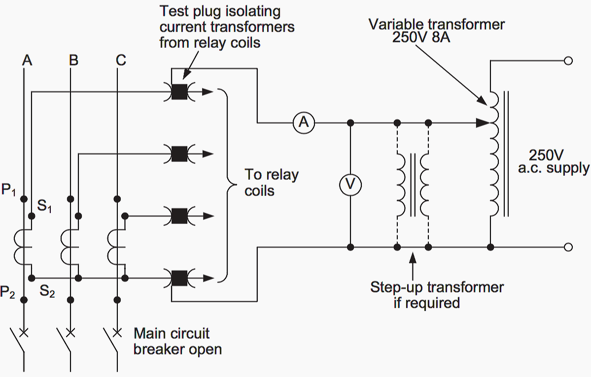
Several points should be checked on each current transformer magnetisation curve. This can be done by energising the secondary winding from the local mains supply through a variable auto-transformer while the primary circuit remains open. See Figure 2.
The characteristic is measured at suitable intervals of applied voltage, until the magnetising current is seen to rise very rapidly for a small increase in voltage. This indicates the approximate knee-point or saturation flux level of the current transformer.
The magnetising current should then be recorded at similar voltage intervals as it is reduced to zero.
Figure 2 – Testing current transformer magnetising curve
Care must be taken that the test equipment is suitably rated. The short-time current rating must be in excess of the CT secondary current rating, to allow for measurement of the saturation current. This will be in excess of the CT secondary current rating. As the magnetising current will not be sinusoidal, a moving iron or dynamometer type ammeter should be used.
It is often found that current transformers with secondary ratings of 1A or less have a knee-point voltage higher than the local mains supply. In these cases, a step-up interposing transformer must be usedto obtain the necessary voltage to check the magnetisation curve.
Voltage transformer tests
Voltage transformers require testing for polarity, ratio and phasing.
Polarity check of voltage transformer
The voltage transformer polarity can be checked using the method for CT polarity tests. Care must be taken to connect the battery supply to the primary winding, with the polarity ammeter connected to the secondary winding. If the voltage transformer is of the capacitor type, then the polarity of the transformer at the bottom of the capacitor stack should be checked.
Ratio check of VT
This check can be carried out when the main circuit is first made live. The voltage transformer secondary voltage is compared with the secondary voltage shown on the nameplate.
Namplate of a single phase voltage transformer (photo credit: emadrlc.blogspot.com)
Phasing check of VT
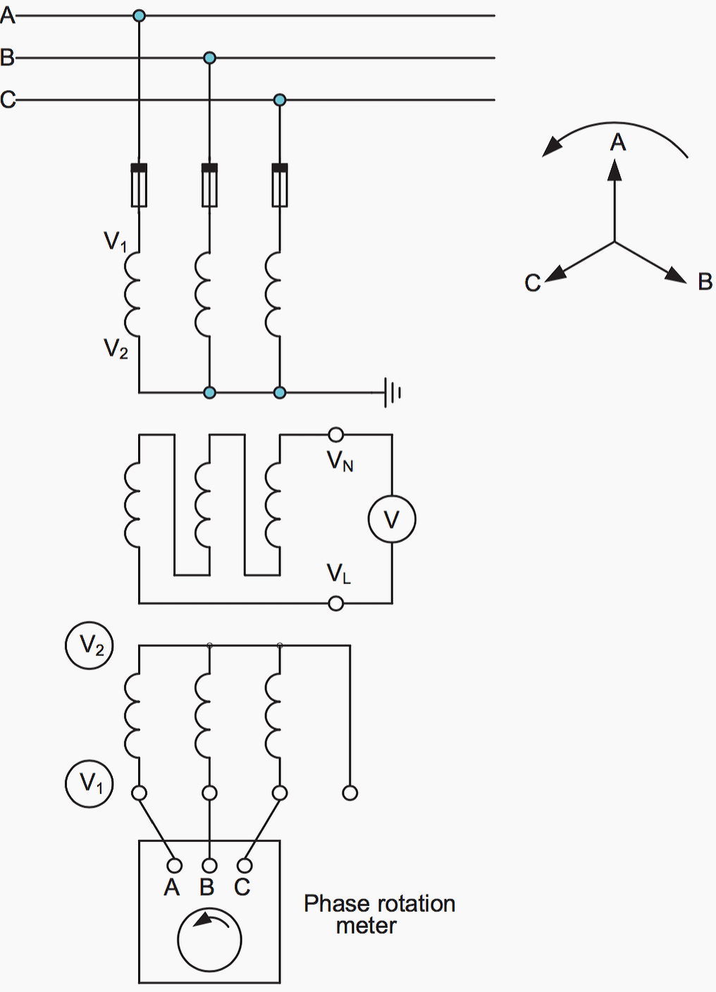
The secondary connections for a three-phase voltage transformer or a bank of three single-phase voltage transformers must be carefully checked for phasing. With the main circuit alive, the phase rotation is checked using a phase rotation meter connected across the three phases, as shown in Figure 3 below.
Provided an existing proven VT is available on the same primary system, and that secondary earthing is employed, all that is now necessary to prove correct phasing is a voltage check between, say, both ‘A’ phase secondary outputs. There should be nominally little or no voltage if the phasing is correct.
However, this test does not detect if the phase sequence is correct, but the phases are displaced by 120o from their correct position, i.e. phase A occupies the position of phase C or phase B in Figure 3.
This can be checked by removing the fuses from phases B and C (say) and measuring the phase-earth voltages on the secondary of the VT. If the phasing is correct, only phase A should be healthy, phases B and C should have only a small residual voltage.
Figure 3 – Voltage transformer phasing check
Correct phasing should be further substantiated when carrying out ‘on load’ tests on any phase-angle sensitive relays, at the relay terminals. Load current in a known phase CT secondary should be compared with the associated phase to neutral VT secondary voltage.
The phase angle between them should be measured, and should relate to the power factor of the system load.
If the three-phase voltage transformer has a broken-delta tertiary winding, then a check should be made of the voltage across the two connections from the broken delta VN and VL, as shown in Figure 3 above. With the rated balanced three- phase supply voltage applied to the voltage transformer primary windings, the broken-delta voltage should be below 5V with the rated burden connected.
Protection relay setting checks (alarm and trip settings)
At some point during commissioning, the alarm and trip settings of the relay elements involved will require to be entered and/or checked. Where the complete scheme is engineered and supplied by a single contractor, the settings may already have been entered prior to despatch from the factory, and hence this need not be repeated.
The method of entering settings varies according to the relay technology used. For electromechanical and static relays, manual entry of the settings for each relay element is required. This method can also be used for digital/numerical relays.
However, the amount of data to be entered is much greater, and thereforeit is usual to use appropriate software, normally supplied by the manufacturer, for this purpose. The software also makes the essential task of making a record of the data entered much easier.
Once the data has been entered, it should be checked for compliance with the recommended settings as calculated from the protection setting study. Where appropriate software is used for data entry, the checks can be considered complete if the data is checked prior to download of the settings to the relay.
Otherwise, a check may required subsequent to data entry by inspection and recording of the relay settings, or it may be considered adequate to do this at the time of data entry.The recorded settings form an essential part of the commissioning documentation provided to the client.
Resource // Network protection and automation guide – Areva
767 Teachers Jobs and Civil Services in Zabul (IARCSC) Jobs in Afghanistan
Independent Administrative Reform Civil Service Commission (IARCSC) of Afghanistan announced vacancies at 13 provinces as Teachers and Civil Services in Rank of 4 and 5. this job opportunity is only for Zabul province. If you want to visit other provinces you can also click here.
Organization: Independent Administrative Reform Civil Service Commission (IARCSC)
Location: Zabul
Position title: Teachers and Civil Services
Gender: Male and Female
Deadline: 10. Sept. 2020
How to Apply
Please read the instructions for the various vacancies of the group exams carefully before applying for the jobs. Enter the exact title of the post, ministry, department, position of the post in the application form. You only have the right to apply for one position and in case of multiple requests, you will be excluded from the competition process.
After filling in the application form, attach your photo to the application form and submit it to the relevant authorities from Sunday (August 29) to Thursday (September 10), along with a copy of your ID and educational documents.
The output of a PV module is not stable it depends on irradiation, temperature etc., thus, we need fixed conditions in order to compare them, size and design our installation. These conditions are called as standard test conditions (STC):
a) Incident irradiance on the PV module surface: 1000W/m²
Figure 1 – The 4 curve of a PV module proportionally to irradiance
We consider that the output power of the module is the point of the IV curve which shapes the greatest area. As we can see the irradiance influences mostly the current.
b) Cell temperature: 25°C
Figure 2 – The output of a PV module proportionally to cell temperature
We consider that the output power of the modules is the point of the IV curve which shapes the greatest area. As we notice the output voltage of a PV module depends mostly on its temperature.
c) Air Mass: 1.5
The Air Mass is the path length which light takes through the atmosphere normalized to the shortest possible path length (that is, when the sun is directly overhead AM=1).
The Air Mass quantifies the reduction in the power of light as it passes through the atmosphere and is absorbed by air and dust.
The Air Mass is defined as:
AM = 1 / cos(Θ)
Figure 4 – Air Mass 1.5
2. PV Modules
All the datasheets include their electrical characteristics data in STC. For instance:
El. characteristics
Unit
Value
Nominal output (Pmpp)
W
280
Voltage at Pmax (Vmpp)
V
36.5
Current at Pmax (Impp)
A
7.7
Open circuit voltage (Voc)
3. String and Array PV Modules
Is a series electrical connectivity of PV modules. An example of string is the following:
Figure 5 – A string consist of 18 PV modules
Assuming that our PV module’s output at STC is: Imp 7A, Vmp 30V, 210W If we will measure at points 1 and 2 we will find: 7A and 540V (18 PV modules X30V) and we get 3,78kW
An example of Array (parallel strings)
Figure 6 – Two parallel strings each one consists of 18 PV modules
If we will measure at points 3 and 4 we will find: 14A and 540V (18 PV modules X30V) and we get 7,56kW.