Monday, 30 December 2024

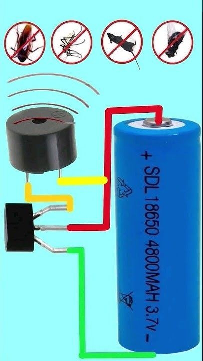
Mosquito and pest repellent circuit and components

This image depicts a simple electronic circuit designed to repel mosquitoes and pests using ultrasonic sound.
Here's a breakdown of the components and their function:
1. Ultrasonic Transducer: The black cylindrical component at the top left is an ultrasonic transducer. It converts electrical signals into ultrasonic sound waves, which are above the frequency range that humans can hear but can be effective in repelling certain insects and small animals.
2. Battery: The large blue component is a rechargeable battery with a capacity of 4800mAh and a voltage of 3.7V. This battery provides the necessary power for the circuit.
3. Transistor: The black component with three leads is a transistor, likely a BJT (Bipolar Junction Transistor). It acts as a switch or amplifier in this circuit, controlling the flow of current to the ultrasonic transducer.
4. Wiring:
• Red Wire: Connects the positive terminal of the battery to the collector of the transistor and one terminal of the ultrasonic transducer.
• Green Wire: Connects the negative terminal of the battery to the emitter of the transistor and the other terminal of the ultrasonic transducer.
• Yellow Wire: Connects the base of the transistor to the circuit, likely to control the transistor's switching action.

How It Works:
- The battery provides a constant voltage to the circuit.
- The transistor is configured to oscillate or switch rapidly, creating pulses of current that drive the ultrasonic transducer.
- The ultrasonic transducer converts these electrical pulses into ultrasonic sound waves, which are emitted into the environment.

Purpose:
• Pest Repellent: The ultrasonic sound waves are intended to be at frequencies that are uncomfortable or disorienting to pests like mosquitoes, rodents, and other insects, encouraging them to leave the area.

Considerations:
• Effectiveness: While ultrasonic devices are marketed as pest repellents, their effectiveness can vary depending on the specific pests and environmental conditions.
• Safety: These devices are generally considered safe for humans and pets, as the ultrasonic frequencies are typically beyond human hearing range.

This circuit is a basic example of how ultrasonic technology can be used for pest control, and it's a common DIY project for those looking to create their own pest repellent devices.
Sunday, 29 December 2024

What's the meaning of this B/500/D/W/R symbol in a rebar bars?

✨ The meaning of symbols in rebar bars
B/500/D/W/R

B: (Bar) 🔹

It is the code for skewers used in reinforced concrete and is often not written on Sikhs.

🔹500:

The yield stress in MPa is the value considered in the design of structural elements.

🔹D: (Ductility)

Degrees of longitality (A, B, C, D) and D are the only acceptable degree for structures resistant to earthquake loads.

🔹W: (Weld)

It means that iron is allowed to be welded and in case of replacing it with a police (-) means that the iron is not allowed to be welded and in this case it cannot be used in any constructional element with welding connections such as axial tensile elements or zur-resistant frim sections that are not allowed by overlay joints.

🔹R: (Rough)

The type of sikh in terms of texture has protrusions (misser) and P is in the case of smooth iron.

Why does power factor improves with capacitor banks in motor circuits?

Power factor improvement with capacitor banks in motor circuits primarily revolves around how capacitors affect the phase relationship between voltage and current in AC circuits.
Here's a detailed explanation:
Understanding Power Factor
• Power Factor (PF) is the ratio of real power (used to perform work) to apparent power (the product of the current and voltage). It is expressed as:
• Inductive Loads like motors introduce a lag in the current waveform with respect to the voltage, which decreases the power factor (makes it more lagging). This lag is due to the magnetic fields within the motor windings that store and release energy, acting somewhat like inductors.

Role of Capacitors
• Capacitors, when connected in parallel to inductive loads, introduce a leading current. This means the current through the capacitor leads the voltage by approximately 90 degrees.

• Cancellation of Reactive Power: 
- Inductive loads consume reactive power, which does not do work but increases the current drawn from the supply, leading to inefficiencies.
- Capacitors supply reactive power back into the circuit, which can cancel out the reactive power consumed by the motor's inductance.

How Capacitors Improve Power Factor:
1. Phase Correction: 
• By adding capacitance, you effectively reduce the phase angle \phi/ by making the total current more in phase with the voltage. This is because:
- The capacitive current leads the voltage, while the inductive current lags it. 
- The combination of these currents results in a net current that is closer in phase to the voltage, thus improving the power factor.

2. Reduction in Line Current: 
• With an improved power factor, the current drawn from the source for the same amount of real power decreases. This is because less reactive current is needed, reducing the apparent power and thus the current for a given voltage.

3. Efficiency and Cost Savings:
• Lower current means less energy loss in transmission lines, less heat in equipment, and often, a reduction in utility bills since many power companies charge based on peak demand and power factor.

4. Practical Considerations:
• Sizing: Capacitors must be sized correctly to match the inductive load of the motor to avoid overcorrection, which can lead to leading power factor issues.
• Location: Placing capacitors at or near the motor reduces losses in the wiring between the capacitors and the motor.

In summary, capacitor banks in motor circuits improve power factor by compensating for the inductive reactance of the motor, bringing the power factor closer to unity, thereby enhancing efficiency, reducing current draw, and potentially saving on energy costs.

Clap Switch

This circuit is designed for a clap switch, which turns a light bulb on or off in response to the sound of clapping.
A breakdown of the components and how it works:

Components:

1. Microphone: Converts the sound of clapping into an electrical signal.
2. Transistor (BT136): This is a TRIAC, a type of thyristor used for controlling AC power. It acts as a switch to turn the light bulb on or off.
3. Light Bulb: The load that is being controlled by the circuit.
4. Resistor and Capacitor (not explicitly shown in the image but typically present): These components would be used to filter and condition the signal from the microphone.
How It Works:
1. Sound Detection: When a clap is detected by the microphone, it generates an electrical signal.
2. Signal Processing: This signal is processed through a circuit that typically includes resistors and capacitors to filter out noise and ensure only the clap signal triggers the switch.
3. Triggering the TRIAC: The processed signal then triggers the gate of the TRIAC (BT136). Once triggered, the TRIAC allows current to flow from the AC power source to the light bulb.
4. Light Control: If the light bulb was off, the TRIAC turns it on by allowing the AC current to pass through. If it was on, the next clap would reset the TRIAC, turning the light off.

Usage:
• Home Automation: Such circuits are used in home automation systems where lights or other devices can be controlled by sound, making it convenient for users who might be busy or have their hands occupied.
• Security Systems: Can be used in security systems for silent alarms or to automatically turn on lights in response to unexpected noises.
• Entertainment: In settings like theaters or presentations where clapping can be used to control stage lighting or other effects.

Considerations:
• Sensitivity Adjustments: The circuit might need adjustments to ensure it responds only to claps and not other noises.
• Power Supply: The TRIAC (BT136) is designed to handle AC power, so this circuit is typically used with AC mains voltage, which requires careful handling due to the risk of electric shock.

This type of circuit showcases a practical application of combining simple audio detection with power control in electronics, making everyday interactions with electronic devices more intuitive and user-friendly.