Friday 16 August 2024

TT, IT, TN-S and TN-C Grounding system

Alright, let's dive into the whimsical world of electrical grounding systems, where wires meet the earth in a dance of safety and conductivity:

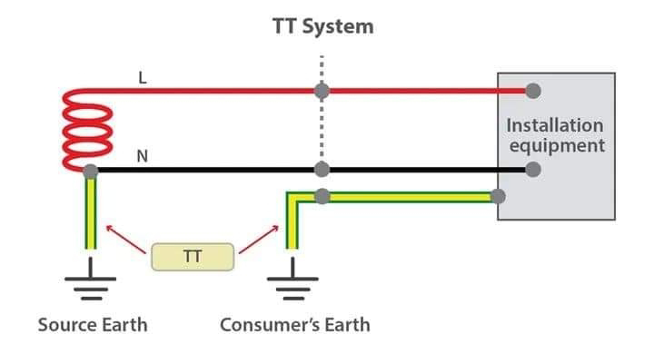
1. TT System: Imagine a scenario where each house or building has its own little earth rod, like planting a flag on the moon, but for electricity. Here, the "T" stands for "Terra" (Earth in French), and it's all about direct connection to earth. The power source (like a transformer) is connected to earth, and so is each consumer's installation, but separately. If there's a fault, the current has to travel through the earth to get back to the source, which might make Mother Earth grumble a bit with all that current. It's like each house has its own private line to the earth's core, which sounds cool but can be tricky for fault detection without an RCD (Residual Current Device).
2. IT System: Here's where things get a bit rebellious. The "I" stands for "Isolé" (Isolated), and the "T" for "Terra". In this system, the power source isn't directly connected to earth; it's isolated, like a lone astronaut in space. The consumer's equipment is earthed, but there's no direct path for fault current back to the source through the earth. This setup is like saying, "We'll deal with faults on our terms." It's often used in places where continuity of service is crucial, like hospitals, because you can keep running even with a first fault, but if a second fault occurs, you might have fireworks.
3. TNS System: Now, let's get organized. TNS stands for "Terra Neutral Separated". Here, the neutral and protective earth conductors are separate all the way from the source to the consumer. It's like having two different highways for your neutral and earth traffic, ensuring they don't mix. This system is like the Swiss Army Knife of grounding systems - versatile, efficient, and it keeps things very clear-cut. If there's a fault, the protective device knows exactly where to look because the earth path is distinct.
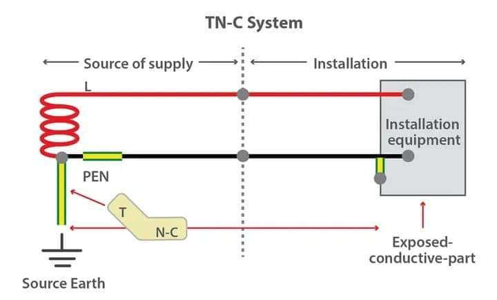
4. TNC System: This one's a bit of a mash-up. TNC stands for "Terra Neutral Combined". Here, the neutral and earth are the same conductor, known as the PEN (Protective Earth and Neutral) conductor. It's like a dual-use lane on a highway where both earth and neutral traffic share the road. This can be efficient but risky if there's a break in this conductor because then, all your earth points could rise to line voltage. It's like if your emergency exit also doubled as the main road, potentially leading to some very confused electrons.
Each of these systems has its quirks, advantages, and scenarios where they shine or where they might cause more headaches than solutions. Remember, in the grand scheme of electrical systems, these are the unsung heroes, keeping us safe from the whims of electricity, one wire at a time.

Thursday 15 August 2024

Types of fuses

1. Cartridge Fuses:
Description: These are enclosed in a cylindrical body, typically made of ceramic or glass, with metal caps on both ends. They are used in both low and high voltage applications.
Types: 
Fast-Acting: Blows quickly for overcurrent protection.
Time-Delay (Slow-Blow): Allows for a brief surge before blowing, useful for devices with high inrush currents like motors or transformers.

2. Bottle Fuses:
Description: Similar to cartridge fuses but specifically designed for high voltage applications. They are often used in power distribution systems where the fuse must handle high voltages without arcing.
Usage: Commonly found in industrial settings or utility power systems.

3. Rewirable Fuses:
Description: These are older types where the fuse element can be replaced. They consist of a base with a carrier that holds a piece of fuse wire.
Advantage: Economical as they can be reused by replacing the wire.
Disadvantage: Not as precise or safe as modern fuse types due to potential for incorrect wire size or material.

4. Low Voltage Fuses:
Description: Designed for circuits where the voltage does not exceed a certain threshold, typically up to 1000V AC or 1500V DC.
Applications: Used in household appliances, electronics, and automotive systems where the voltage is relatively low.

5. Draw Out Fuses:
Description: These are designed for easy replacement without de-energizing the entire system. They can be pulled out for inspection or replacement while the system remains operational.
Usage: Common in switchgear where maintenance or replacement without downtime is crucial.

6. High Voltage Fuses:
Description: Engineered for systems where the voltage can be in the thousands of volts. They are crucial in preventing catastrophic failures in high voltage electrical systems.
Types:
Expulsion Fuses: Use the expulsion effect to quench the arc by gases produced from the fuse material.
Current Limiting Fuses: Designed to limit the let-through current during a fault, reducing the stress on other components.

Each type of fuse has its specific application based on the voltage level, current rating, response time, and the environment in which it's used. The choice of fuse type depends on the protection requirements of the electrical system, including considerations for safety, reliability, and ease of maintenance.

Wednesday 14 August 2024

What is the difference between circuit breaker and isolator?

To understand the differences between Miniature Circuit Breakers (MCB), Molded Case Circuit Breakers (MCCB), and Isolator Switches, let's break down their functionalities, applications, and key characteristics:
1. Miniature Circuit Breaker (MCB)
Purpose: Primarily designed for protection against overcurrent and short circuits in low-voltage installations (up to 100-125A in residential and commercial settings).
Operation: Automatically trips when the current exceeds a safe level, thus breaking the circuit to prevent damage or fire due to overload or short circuits.
Features:
Compact size, suitable for domestic and small commercial applications.
Can be reset manually after tripping.
Typically has a thermal-magnetic operation for overload and short-circuit protection.
Applications: Used in homes, offices, and small industrial setups for protecting circuits from overcurrent.

2. Molded Case Circuit Breaker (MCCB)
Purpose: Similar to MCBs but designed for higher current ratings (from 100A to several thousand amps) and often used in industrial and large commercial settings.
Operation: Also provides protection against overcurrent and short circuits, but MCCBs can handle much higher currents and often come with additional features like adjustable trip settings.
Features:
Larger than MCBs, with a molded case.
Can include features like adjustable trip settings for fine-tuning protection levels.
Often used where higher fault currents are expected.
Applications: Industrial installations, heavy machinery, large commercial buildings, where higher current ratings and more robust protection are needed.

Isolator Switch
Purpose: Not for protection but for isolating parts of an electrical installation for safety reasons during maintenance or repair.
Operation: 
Manually operated to completely disconnect the circuit from the power source.
Does not automatically trip; it must be manually operated.
Features:
Provides a visible break in the circuit, ensuring no current is flowing through the part being worked on.
Often used in conjunction with circuit breakers where the breaker is used for protection and the isolator for maintenance safety.
Applications: 
Found in electrical panels, switchyards, and industrial setups where equipment needs to be safely disconnected for service or replacement.

Key Differences:
a. Functionality:
MCBs and MCCBs are protective devices that automatically disconnect the circuit when a fault is detected.
Isolators are for manual disconnection, not for automatic protection.
b. Usage:
MCBs for lower current ratings, MCCBs for higher currents and more complex protection needs.
Isolators for ensuring safety during maintenance or for permanent disconnection.
c. Resetting:
MCBs/MCCBs can be reset after a fault.
Isolators require manual operation to reconnect.
d. Visibility:
Isolators often provide a visual indication of the circuit's state, which is crucial for safety.

Understanding these differences helps in selecting the right device for specific electrical needs, ensuring both safety and efficient operation of electrical systems.

Tuesday 23 July 2024

Why do wind turbines have 3 blades not 4 or 5?

Why do wind turbines have three blades instead of two or five? Well, it's not because they're trying to be fashionable or anything. It's all about balance, efficiency, and cost-effectiveness.
Having three blades is like finding the Goldilocks zone of wind turbine design. With two blades, you'd have issues with something called "gyroscopic precession," which could cause the turbine to wobble like a drunk penguin. Not ideal. And with more than three blades, you'd face higher manufacturing costs, weight, and more complex maintenance.

Three blades strike a happy medium. They're easier to balance, more aerodynamically efficient, and less likely to cause noise pollution. Plus, they're cheaper to manufacture and maintain. It's like the Goldilocks principle in action: not too few, not too many, just right.

So, the next time you see a wind turbine, give a nod to those three blades. They're not just there for show; they're a carefully calculated choice to maximize efficiency and minimize costs. And that's something we can all get behind.

Technical Answer: 
Wind turbines typically have three blades because of the trade-offs between efficiency, cost, and structural dynamics. 

From an aerodynamic perspective, a three-blade design offers a good balance between power generation and efficiency. With three blades, the turbine can capture more wind energy compared to a two-blade design. More blades would theoretically generate more power, but this is offset by increased weight and cost. 

Structurally, three blades are easier to balance than two, which helps to reduce vibrations and fatigue on the turbine components. This is crucial for ensuring the longevity and reliability of the turbine. 

Additionally, the three-blade design is cost-effective. Manufacturing and maintaining a turbine with more than three blades would significantly increase the cost, due to the additional materials and complexity involved. 

In summary, the three-blade configuration is a compromise that offers a good balance between power generation, structural integrity, and cost.

Friday 19 July 2024

Do you know how busbars are riveted?

Oh, the riveting process of busbar manufacturing! It's like watching a ballet performance, but with more sparks and less tutus. 
In this video, the busbar is being shaped and adjusted to fit the specific requirements of its intended application. It's like a metal origami, but instead of paper, it's made of copper or aluminum. The busbar is bent, punched, drilled, and sometimes even coated with protective materials to make it more durable. 

The process is fascinating, really. It's like watching a blacksmith forge a sword, but instead of a sword, it's a crucial component of electrical systems. The busbar is carefully crafted to ensure it can handle the electrical load and withstand the harsh environments it will be used in.

It's a testament to human ingenuity and our ability to manipulate materials to serve our needs. And who knows, maybe one day busbars will be made of materials we haven't even discovered yet!

Saturday 13 July 2024

My car battery keeps dying. What could be draining the battery?

My car battery keeps dying. What could be draining the battery?
Here are some possible culprits behind a frequently dying car battery:

- Leaving Interior Lights On: Did you accidentally leave dome lights or the trunk light on? Even a small draw can drain a battery over time.
- Parasitic Drain: An electrical component in your car could be malfunctioning and causing a small current draw even when the car is off.
- Dead Battery: The battery itself might be old or damaged and not holding a charge properly.
- Alternator Issues: The alternator is responsible for recharging the battery while the car runs. If it's faulty, it might not be supplying enough power to keep the battery charged.

Friday 12 July 2024

Transformer oil test

Transformer oil test
1. OBJECTIVE: 
To verify dielectric strength of transformer oil from both tank and OLTC. 
2. TEST INSTRUMENTS REQUIRED: 
- Oil sample bottle 
- BDV tester 
3. TEST PROCEDURE: 
3.1. OIL SAMPLING: 
• A clean, dry GLASS container is to be used. The size of the container should be at least three times the size of the test cell. (A container of approximately 1 litre is
sufficient) 
• During sampling, rinse the glass container with little quantity of oil and drain. 
• Fill the container with oil until the container over flows. 
• Do not allow free air space inside the container. 
• Do not allow air bubbles inside the container. 
• Sampled Container should be closed airtight with cork or any other nonreactive material. 
• (Optional). In case the oil is to be transported to a larger distances, ensure that oil is stored in a clean and dry place and transported with utmost 
care. 
• Before filling the oil in the test cell, gently agitate the container without creating air bubbles. 
• Rinse the walls of the test cells with little of oil and drain it. 
• Ensure that the electrodes of the test cell are clean. 
• Fill the oil sample until overflow, into the test cell without formation of air bubbles. 
• Do not start the test for at least for 5 min. after filling the test sample (oil). 
3.2. BREAK DOWN VOLTAGE TEST: 
• The oil sampling to be carried out as per the procedure explained in the sampling instructions. 
• The BDV test to be started after at least 5 minutes from the filling of the sample oil in the test cell. 
• Ensure that the gap between the electrodes is maintained at 2.5mm. 
• Ensure that the electrodes are clean. 
• The rate of rise of the test voltage to be adjusted at 2kV per second. 
• Conduct the BDV test for 5 to 6 times for the same sample with a time interval of at least 3 - 4 minutes between tests. 
• Ensure that between tests, stirring of the test sample is carried out. 
• Record the test results and obtain the average of the test results to obtain 
the Breakdown voltage of the test sample. (Ignore the odd values).

AC 12V-0-12V transformer