Friday, 28 June 2024

What is the function of the oil in a transformer?

What is the function of the oil in a transformer?
The function of transformer oil, also known as insulating oil or dielectric oil, in a power transformer is to perform several critical functions:

Insulation: Transformer oil provides insulation between the transformer windings and other live parts, preventing electrical breakdown and ensuring safe operation.

Cooling: Transformer oil acts as a coolant, dissipating heat generated during transformer operation. It transfers heat away from the core and windings, helping to maintain optimal operating temperatures.

Arc suppression: Transformer oil suppresses and extinguishes electrical arcs that may occur due to internal or external faults, preventing damage to the transformer and associated equipment.

Contaminant removal: The oil circulates through the transformer, capturing and carrying away contaminants such as moisture, dust, and oxidation byproducts that could degrade the insulation and affect transformer performance.

Dielectric strength: Transformer oil has high dielectric strength, which means it can withstand high voltages without breaking down, maintaining the integrity of the insulation system.

Lubrication: Transformer oil provides lubrication to moving parts, such as tap changers, within the transformer, reducing friction and wear.

Corrosion prevention: Transformer oil inhibits the corrosion of metal surfaces within the transformer, protecting the internal components and prolonging the transformer's lifespan.

Wednesday, 26 June 2024

Solar panels vs Solar heaters which one do you need?

In the midst of the load shedding crisis (electricity outages for subscribers), solar energy becomes the solution.
Solar energy: It is the Light and Heat emitted from the sun, and each has a method of utilization.

1. Heat: It is used to heat water through a solar water heater that is installed on top of the building. It is connected to the cold and hot water lines. Through glass panels, it absorbs the sun's rays and transfers the heat to the cold water line.

2. Light: In this case, the sun's rays falling on the solar cells (PV) made of semiconductor materials are converted into electricity, which is used for lighting and powering electrical appliances such as TVs, refrigerators, etc.

This means that solar cells produce electrical energy, while the solar water heater does not produce any electricity, but rather converts the sun's light into heat used for heating.

This post is for people who say that solar cells are not feasible and are expensive. Even if you are not convinced, just use the solar water heater. It is easy to install and does not require much maintenance, and it reduces the use of electric or gas water heaters.

Solar energy is the solution.

I hope the difference between the two has been clarified, as some of us get confused about it.

Phase-to-Ground (SLG ) Fault Through High Resistance

Phase-to-Ground (SLG ) Fault Through High Resistance:
1- High-resistance faults can occur on EHV systems, and normally such faults are cleared from the system by backup directional ground time overcurrent relays. These types of faults offer a challenge to relaying systems that are based on operating principles using impedance (distance) measurements. In this case, the delayed clearing is acceptable since these high-resistance faults have less impact on the transient stability of the system. 

2- Protection of EHV lines should be based on applying redundant ground directional overcurrent protection to provide a guarantee to clear high-resistance ground faults and to sense open-phase conditions.

3-The communication schemes are used nowadays to provide faster tripping for the high resistive fault and open phase (AIDED SCHEME).

4- for the communication scheme, practically I think negative sequence voltage polarization to identify the forward direction of the fault, in many cases more reliable than zero sequence polarization voltage especially in parallel lines since the zero sequence can be affected by mutual coupling and cause the relay to mal-operate during external faults resulting in cascade trippings.

What do you think is better to be used in the DEF-aided scheme, negative sequence voltage polarization or zero sequence?

Tuesday, 11 June 2024

Control motor speed with potentiometer and VFD

A potentiometer, also known as a "pot," is a variable resistor that can change its resistance value when you turn it. It's like a tiny, mechanical wizard that can control the flow of electrical magic.

On the other hand, a variable frequency drive (VFD) is a device that can change the speed of an electric motor by altering the frequency of the power it provides. It's like a DJ spinning the record at different speeds to make the music faster or slower.
Now, when you connect a potentiometer to a VFD, you're essentially giving the VFD a way to control the motor speed using a manual input. It's like having a volume knob for your motor's RPMs.
Here's a simple breakdown of the connection:

Wiper (center tap) to VFD's speed control input: This is the heart of the connection. The wiper, or the center tap of the potentiometer, sends a voltage signal to the VFD's speed control input. This signal tells the VFD how fast to spin the motor.
One outer end of the potentiometer to the VFD's positive terminal: This provides power to the potentiometer. Think of it as giving the wizard a battery to work his magic.
The other outer end of the potentiometer to the VFD's negative terminal: This completes the circuit and allows the potentiometer to do its thing.

By turning the potentiometer, you're changing the voltage signal sent to the VFD, which in turn changes the motor speed. It's like turning the volume knob on your stereo, but instead of changing the music volume, you're changing the motor RPMs.

Just remember to use a shielded cable to connect the potentiometer to the VFD, and make sure to follow the manufacturer's instructions for any specific settings or adjustments.

Saturday, 8 June 2024

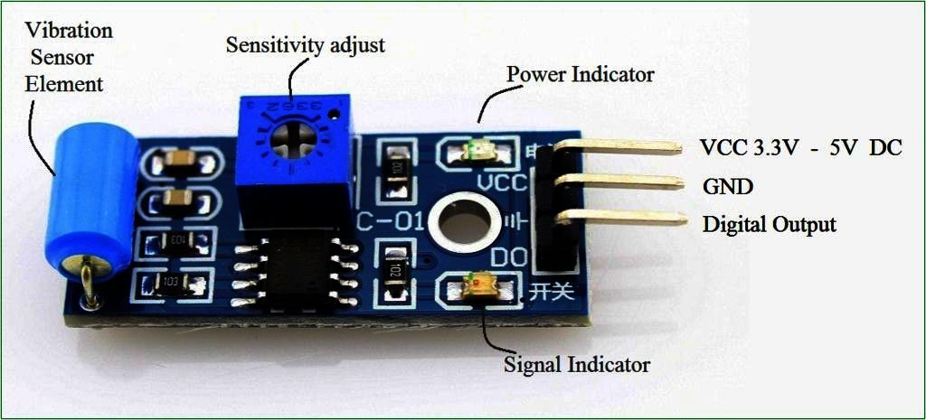
Vibration Sensor

A vibration sensor is a device that detects mechanical vibrations. It measures the vibration levels in your machine and alerts you to any potential problems, like equipment failure or worn parts that need replacement.
There are several types of vibration sensors out there, each with its own unique characteristics and applications.
1. Accelerometers: These are the most common type of vibration sensor. They measure acceleration, which is the rate of change of velocity. Accelerometers can detect vibrations across a wide frequency range and are often used in applications such as machinery monitoring, seismic monitoring, and vehicle dynamics testing.
2. Velocity sensors: These sensors measure the velocity of vibration, which is the rate of change of displacement. Velocity sensors are often used in applications where high-frequency vibration needs to be monitored, such as in the aerospace industry.
3. Displacement sensors: These sensors measure the displacement of a vibrating object. Displacement sensors are often used in applications where low-frequency vibration needs to be monitored, such as in structural health monitoring.
4. Strain gauge sensors: These sensors measure the strain or deformation of a structure due to vibration. Strain gauge sensors are often used in applications where the vibration needs to be monitored in real-time, such as in bridge monitoring.
5. Piezoelectric sensors: These sensors use the piezoelectric effect to convert mechanical vibrations into electrical signals. Piezoelectric sensors are often used in applications where high sensitivity is required, such as in medical diagnostics and acoustic measurements.

Now, the question is, which type of vibration sensor is right for you? Well, that depends on your specific needs and application.

Good News: Kamal Khan Dam Power House Turbines Complete, Energy Generation Begins to Power the Population

Good News: Kamal Khan Dam Power House Turbines Complete, Energy Generation Begins to Power the Population

We are thrilled to announce a momentous achievement in the energy sector—the completion of the turbine installation at the Kamal Khan Dam Power House! With great delight, we share the news that energy generation has commenced, and this significant milestone marks a new era of power supply for the population.

The Kamal Khan Dam, a monumental infrastructure project aimed at harnessing the immense hydroelectric potential of the region, has reached a major milestone with the successful installation and commissioning of its power house turbines. These turbines, meticulously designed and engineered to harness the power of water, are now in full operation, converting the force of the flowing river into clean and sustainable electricity.

With this momentous development, the Kamal Khan Dam Power House is now generating a substantial amount of electricity, which will directly benefit the local population. The reliable and renewable energy generated by the dam will play a crucial role in meeting the growing power demands of the region, fueling economic growth, and improving the quality of life for residents.

The commencement of energy generation from the Kamal Khan Dam Power House signifies a transformative shift towards sustainable energy sources and reduces dependence on fossil fuels. By harnessing the power of water, this hydroelectric facility will significantly contribute to mitigating carbon emissions, promoting environmental preservation, and combating climate change.

The power generated from the Kamal Khan Dam will be distributed through an extensive grid network, ensuring that homes, businesses, schools, and hospitals receive a steady and reliable supply of electricity. This development will not only enhance the living standards of the local population but also attract investments, create job opportunities, and stimulate economic growth in the surrounding areas.

We commend the dedicated efforts of the engineers, technicians, and workers who have worked tirelessly to make this achievement possible. Their expertise, perseverance, and commitment to excellence have transformed the vision of the Kamal Khan Dam into a reality, bringing sustainable energy and progress to the region.

This landmark accomplishment in the energy sector brings us closer to a brighter and greener future. The Kamal Khan Dam Power House turbines are now generating power, lighting up homes, businesses, and lives. With this clean energy source, we are paving the way for a sustainable and prosperous future for generations to come.

Friday, 7 June 2024

Why does a capacitor blocks DC but passes AC?

Picture this: a capacitor is like a bouncer at an exclusive club. Direct current (DC) is like a steady stream of partygoers trying to get in. The capacitor says, "No way, Jose! I'm not letting you in unless you're on the VIP list." And since DC is a constant voltage, it's not on the VIP list, so it gets blocked.
Now, alternating current (AC) is a whole different story. It's like a group of partygoers who are doing the wave, jumping up and down in a pattern. The capacitor says, "Hey, you're doing the wave! You're on the VIP list! Come on in!" And since AC is a changing voltage, it's on the VIP list, so it gets to pass through the capacitor.

In technical terms, a capacitor blocks DC because it has a high reactance to DC voltage, which means it resists the flow of direct current. On the other hand, it passes AC because the changing voltage of AC causes the capacitor to charge and discharge, allowing the current to flow through.

So, to sum it up, a capacitor is like a picky eater who only lets the cool kids (AC) in, while keeping the boring ones (DC) out.

Now let's discuss it more technically:

At the heart of this phenomenon lies the concept of impedance. Impedance is the total opposition that a circuit presents to an alternating current (AC) or voltage. It is composed of two parts: resistance (R) and reactance (X). Resistance is the opposition to direct current (DC), while reactance is the opposition to AC.

In a capacitor, the reactance is known as capacitive reactance (XC). The formula for capacitive reactance is:

• XC = 1 / (2πfC)

Where:
• XC is the capacitive reactance in ohms
• f is the frequency of the AC signal in hertz (Hz)
• C is the capacitance in farads (F)
• π is approximately 3.14

When a DC voltage is applied to a capacitor, the frequency (f) is 0 Hz. Plugging this into the formula, we get:

• XC = 1 / (2π * 0 * C) = 1 / 0 = infinity

This means that the capacitor presents an infinite impedance to DC, effectively blocking it.

On the other hand, when an AC voltage is applied to a capacitor, the frequency is non-zero. As the frequency increases, the capacitive reactance decreases, allowing the AC to pass through the capacitor. This is because the capacitor charges and discharges with the changes in the AC voltage, allowing the current to flow.

In summary, a capacitor blocks DC because it presents an infinite impedance to it, while it passes AC because the capacitive reactance decreases with increasing frequency, allowing the current to flow.